background image

2001 NEW

11

2001 NEW

2001 NEW

BASIC OPERATION

5


D

Using the keypad

 When selecting a Useo channel

1.   Push the keypad keys to enter the channel 

number.

2.  Push [ENT] to set.

Example

•  Selecting CH 41:


[4 

ghi

] → [1] → [ENT]

•  Selecting CH 128:


[1] → [2 

abc

] → [8 

tuv

] → [ENT]

 When selecting an ITU duplex channel

1.   Push the keypad keys to enter the channel 

number.

2.  Push [ENT] to set.

Example


•  Selecting CH 401:


[4 

ghi

] → [0] →[1]→ [ENT]


•  Selecting CH 2505:


 [2 

abc

] → [5 

Jkl

] →[0] → 

[5 

Jkl

] → [ENT]

NOTE:


•  See the Channel and Channel Group list below.


•  Pushing [CLR] clears the entered digits and return to the 

previous channel.

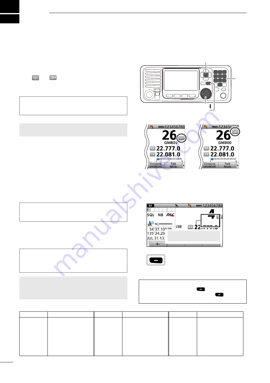
 When selecting an ITU simplex channel

1.   Push the keypad keys to select a frequency band.

2.   

Push the left most Software Key to enter “– ” 

(dash).


3.   Push the keypad keys to enter the channel 

number.

4. 

Push [ENT] to set.

Example


Selecting CH 

4-1

:


[4 

ghi

] → 

 →[1]→ [ENT]


Selecting CH 25-2:


[2 

abc

] → [5 

Jkl

] → 

 → 

[2 

abc

] → [ENT]


D

 Using the channel and gooup selectoo

1. 

 Push [CH/GRP] to toggle the Channel Select 

mode or the Group Select mode.


• “ 

 ” or “ 

 ” is displayed.

2. 

 Rotate [CH/GRP] to select a channel or group.

Example

When selecting the Group Select mode, the User 

channels change in 20 channel steps.

NOTE:

 See the Channel and Channel Group list 

below.


[CH/GRP]

• Channel Select mode

• Group Select mode


  Selecting a Channel oo  

Group

Push

[ENT]

KEY PAD

[CLR]

• Channel and Channel Group list

Channel No.

Descoiption

Channel No.

Descoiption

Channel No.

Descoiption

1 ~ 160

401 ~ 429
4-1 ~ 4-9
601 ~ 608
6-1 ~ 6-9
801 ~ 837
8-1 ~ 8-9

User CH*
4 MHz ITU duplex CH 
4 MHz ITU simplex CH
6 MHz ITU duplex CH
6 MHz ITU simplex CH
8 MHz ITU duplex CH
8 MHz ITU simplex CH

1201 ~ 1241
12-1 ~ 12-9

1601 ~ 1656

16-1 ~ 16-9
1801 ~ 1815
18-1 ~ 18-9

2201 ~ 2253

12 MHz ITU duplex CH
12 MHz ITU simplex CH
16 MHz ITU duplex CH
16 MHz ITU simplex CH
18 MHz ITU duplex CH
18 MHz ITU simplex CH
22 MHz ITU duplex CH

22-1 ~ 22-9

2501 ~ 2510

25-1 ~ 25-9
C1-1 ~ C1-21
C2-1 ~ C2-31

22 MHz ITU simplex CH
25 MHz ITU duplex CH
25 MHz ITU simplex CH
C1 channels
C2 channels

*


[GRP] changes in 20 channel steps. 

Selected frequency band is 

briefl y displayed.

Содержание IC-GM800

Страница 1: ...INSTRUCTION MANUAL GM800 MF HF MARINE TRANSCEIVER...

Страница 2: ...about your ship Type Length Color The number of people on board EXPLICIT DEFINITIONS WORD DEFINITION RDANGER Personal death serious injury or an explosion may occur RWARNING Personal injury fire haza...

Страница 3: ...tors on the rear panel do not meet IPX7 NOTE If the remote controller s waterproof protection appears defective carefully clean it with a soft damp fresh water cloth then dry it before operating The r...

Страница 4: ...hould be installed as high as possible for maximum efficiency and the installation height should be at least 2 0 meters above any accessible position In the case where an antenna cannot be installed a...

Страница 5: ...Group call 45 D D Sending a Geographical call 47 D D Sending a Position Request call 50 D D Sending a Position Request acknowledgement 51 D D Sending a Polling Request acknowledgement 52 D D Sending...

Страница 6: ...ment in the maintenance log The entries requires signatures by the authorized licensed technician performing or supervising the work RADIO LICENSES 1 SHIP RADIO STATION LICENSE You need a current ship...

Страница 7: ...GPS IN t CONTROLLER CONNECTOR CONTROLLER Connect to the supplied controller y MODEM SOCKET AF MOD p 87 Connect to an external terminal unit for SSB mode operation through an RS 232C cable D sub 15 pi...

Страница 8: ...turn the transceiver ON or OFF i VOLUME DIAL VOL Rotate to adjust the speaker volume level Push 1 5 times to display the setting screens Pushing once The Volume Setting window is displayed Pushing twi...

Страница 9: ...are Keys for various functions The key s function is displayed above them as shown below DSelecting the Software Key function When or is displayed beside the key icon pushing or scrolls the Software K...

Страница 10: ...sh to turn the Clarity Control function ON or OFF p 16 TX Freq Monitor Push to check and monitor the transmit frequency p 15 SP Push to turn the speaker output ON or OFF AGC Push to turn the Automatic...

Страница 11: ...layed when the Clarity function is ON The number displays the added or subtracted frequency SIMP Displayed when a Simplex channel is selected DUP Displayed when a Duplex channel is selected J3E H3E LS...

Страница 12: ...r that NO POSITION will be displayed DATE AND TIME AREA The current time is displayed when valid GPS data is received or manually enter the time The date information is displayed when the RMC GPS sent...

Страница 13: ...Push CLR to cancel the entry In that case the transceiver displays Push ENT to Register Your MMSI again 3 Enter your 9 digit MMSI code 4 After entering the 9th digit push ENT The MMSI CONFIRMATION sc...

Страница 14: ...est ACK Medical Transports Ships and Aircraft Distress Scanning Receiver 10 Second Delay Alarm Status Safety Routine Warning Self Terminate Discrete Auto Print DSC Loop Test Radio Settings User CHAN I...

Страница 15: ...h MENU to return to the Main screen Rotate Push CH GRP Rotate Push CH GRP Rotate Push CH GRP Innooraaton L You can use the following key functions in the MENU screen FUNCTION ACTION Select Rotate CH G...

Страница 16: ...nnel Select mode or the Group Select mode or is displayed 2 Rotate CH GRP to select a channel or group Example When selecting the Group Select mode the User channels change in 20 channel steps NOTE Se...

Страница 17: ...WR is displayed during the transmission check your antenna system 5 Speak into the microphone at your normal voice level 6 Release PTT to receive is displayed NOTE Foo the Time out Timeo TOT function...

Страница 18: ...s adjustable in 7 levels and OFF OFF is selectable only in the Day mode Push Rotate Push CH GRP OTHER FUNCTIONS AND OPERATIONS 6 Backlight function The function display and keys can be backlit for bet...

Страница 19: ...he frequency range between user channels Ch 159 Ch 160 1 Push or until SQL is displayed in the Software Key area 2 Push SQL to turn OFF the squelch function 3 Push or until Scan is displayed in the So...

Страница 20: ...oises that come from engine ignitions However when the received strong signals are distorted adjust the Noise blanker level or turn OFF the function 1 Push or until NB is displayed in the Software Key...

Страница 21: ...F gain level setting window is displayed 3 Rotate CH GRP to adjust the RF gain level D DClarity Control function With the Clarity Control function you can slightly shift the receive frequency without...

Страница 22: ...ating RX frequency and push ENT Otherwise it automatically returns to the preset value soon 4 Push RX TX to select the TX mode The TX icon lights blue 5 Enter a TX frequency then push ENT NOTE Quickly...

Страница 23: ...ollowing instructions are for a User channel Editing However you can set an ITU Simplex channel name in the same way 1 Enteoing the Channel Edit scoeen 1 Push MENU 2 Select Radio Settings 3 Select Use...

Страница 24: ...Setting a channel name You can set a channel name of up to 10 characters for each User and ITU channel This may be helpful to indicate the frequency s use or a ship s name 11 Select Name 12 Enter a ch...

Страница 25: ...11 10 9 8 7 6 5 3 4 2 Quick Refeoence Assigning a function You can assign some different Software Key functions to a key between Soft Key 5 and Soft Key 20 p 5 You can also assign some Software Key f...

Страница 26: ...place Example Push 3 Rotate Push CH GRP Rotate Push CH GRP Rotate Push CH GRP Rotate Push CH GRP Assigning a function 6 Select a Software Key function Example Backlight Backlight is assigned to Push 3...

Страница 27: ...U 2 Select Configuration 3 Select Assignment 4 Select P Key Assignment Rotate Push CH GRP Rotate Push CH GRP Rotate Push CH GRP 5 Select a Software Key function Example Mode Mode is assigned to P 6 Pu...

Страница 28: ...ect Call Frequency Rotate Push CH GRP Rotate Push CH GRP Push Rotate Push CH GRP Push Rotate to select a character CH GRP Rotate Push CH GRP You can enter a total of 100 DSC address IDs and assign a n...

Страница 29: ...fter entering push or to select Done and push ENT 10 Select Name 11 Enter an Individual ID name After entering push or to select Done and push ENT 12 Push Save 13 Push OK to save the ID The entered In...

Страница 30: ...ID L The first 2 digits are 0 for any Coast station ID 7 Select Call Frequency 8 Enter an RX frequency After entering push or to select Done and push ENT 9 Enter a TX frequency After entering push or...

Страница 31: ...eturn to the Main screen DDeleaing mn enaered ID 1 Push MENU MENU screen is displayed 2 Rotate CH GRP to select DSC Settings DSC SETTING screen is displayed 3 Select Individual ID or Group ID INDIVIDU...

Страница 32: ...Select DSC Settings 3 Select Position Input 4 Enter your latitude L To select N North latitude or S South latitude push any key when the cursor is on the N or S position 5 After entering push or to se...

Страница 33: ...UTC Time 13 20 When no position data and time are set No Position and No Time are displayed LInformatio L While entering To move the cursor Rotate CH GRP To correct the entry Move the cursor to the c...

Страница 34: ...mode has 2 statuses Active and Hold When you send the repeat call or send an acknowledgement to the caller station push Active to display the Active window Active window L is displayed on the active...

Страница 35: ...ess call D DSimple call 1 Confirm no Distress call is being received 2 Lift up the key cover then hold down DISTRESS until Transmitting is displayed to send a Distress call 3 After sending Waiting for...

Страница 36: ...alid In that case go to Step 3 4 Select Position The Latitude Position Entry screen is displayed 5 Enter your position data and time See page 27 for entering details Step 3 Setting a communication fre...

Страница 37: ...ed distress Position data The latest GPS or manual input position data is retained for 23 5 hours unless you turn OFF the transceiver While holding down DISTRESS count down beeps sound and both the ke...

Страница 38: ...r then hold down DISTRESS until Retransmitting is displayed to resend the call While holding down DISTRESS count down beeps sound and both the key and display backlighting blink NOTE To cancel a Distr...

Страница 39: ...the Distress Cancel call push Back 3 After sending the following screen is displayed Push Select FREQ 4 Select a frequency to send a voice cancel message and push ENT L The check mark shows that the D...

Страница 40: ...Push Select FREQ 4 Select a frequency to send a voice cancel message and push ENT L The check mark shows that the Distress call on the selected frequency is canceled by sending voice cancel message 5...

Страница 41: ...he coast station if the coast station requires IMPORTANT Distress acknowledgements should be transmitted only on the 2187 5 kHz according to regulations ITU R 493 13 When you receive a Distress call o...

Страница 42: ...one Else and Distress Relay Call with Distress Call Log NOTE DO NOT push DISTRESS to transmit a distress relay call It is used for only your own distress calls To transmit the Distress Relay call with...

Страница 43: ...ll Log is displayed after receiving the Distress call DO NOT select displayed Individual IDs for DROBOSE 8 Enter the 9 digit Distress ID MMSI ID code of the ship in distress that you want to help Afte...

Страница 44: ...select Done and push ENT See page 27 for position entering details 13 Select Call Frequency 14 Select an option Example 2187 5 kHz 15 Push Call to send the Distress Relay call 16 After sending the fol...

Страница 45: ...2 Select Message Type 3 Select a message type Example Individual 4 Select Address 5 Select a coast station address or Manual Input Example COAST A NOTE When you select Manual Input in this step push t...

Страница 46: ...all to send the Distress Relay call 11 After sending the following screen is displayed See page 29 for details of the software key function in the DSC Task mode 12 Hold down PTT to communicate with a...

Страница 47: ...DSC Task mode is displayed on the Task tab 3 Push to scroll the software key function 4 Push ACK Relay The call contents screen is displayed The call contents screen is displayed L Rotate CH ENT to v...

Страница 48: ...ress 3 Select an Individual address or Manual Input Example STATION A NOTE When you select Manual Input in this step push the keypad to manually enter an Individual ID 4 Select Category 5 Select an op...

Страница 49: ...push the keypad to manually enter a communication frequency 8 Send an Individual call 9 After sending Waiting for ACK is displayed 10 When receiving the acknowledgement Alarm sounds The following win...

Страница 50: ...thout any changes ACK Unable Send an acknowledgment but you cannot make a communication ACK New CH Send an acknowledgment You can specify the Voice Communication channel The call contents screen is di...

Страница 51: ...2 1 NOTE When you select Manual Input in this step push the keypad to manually enter the DSC call frequency 6 Select Comm Frequency 7 Select a communication frequency or Manual Input Example SHIP 2M N...

Страница 52: ...Quadrant 6 Enter the area information Push Rotate Push CH GRP Rotate Push CH GRP Rotate Push CH GRP Rotate Push CH GRP When selecting Circle You can send a Geographical call within the area covered b...

Страница 53: ...You 10 Longitude 100 W To Your Right 20 1 Enter the latitude of your position After entering select Done and push ENT 2 Enter the longitude of your position After entering select Done and push ENT Pu...

Страница 54: ...M NOTE When you select Manual Input in this step push the keypad to manually enter a communication frequency 13 Push Call to send the Geographical call 14 After sending the following screen is display...

Страница 55: ...e Non Distress 2 Select Message Type 3 Select Position 4 Select Address 5 Select an Individual ID or Manual Input Example STATION A NOTE When you select Manual Input in this step push the keypad to ma...

Страница 56: ...isplayed on the Task tab 3 Push to scroll the software key function 4 Push a key to select an acknowledgement option Example ACK Able LInformatio L ACK Able Send an acknowledgment with position data a...

Страница 57: ...otate CH GRP to confirm the contents Push any Push Push 5 Push Call to send the Polling Request acknowledgement Your position data and time are transmitted 6 Push Standby Mode to return to the Standby...

Страница 58: ...14 5 kHz 8 Push Call to send the Test call 9 After sending the following screen is displayed See page 29 for details of the software key function in the DSC Task mode 10 Push Standby Mode to return to...

Страница 59: ...ft call The Medical Transports call informs all ships by urgency priority that your ship is carrying a patient in need of medical treatment The Ships and Aircraft call informs all ships that your ship...

Страница 60: ...10 N 100 W 20 N 100 W 10 N 80 W 20 N 80 W Example Latitude 20 N Behind You 10 Longitude 100 W To Your Right 20 1 Enter the latitude of your position After entering select Done and push ENT Push Rotate...

Страница 61: ...CH GRP 7 Select Call Frequency 8 Select an option Example 8414 5 kHz Rotate Push CH GRP Rotate Push CH GRP 9 Select Comm Frequency 10 Select a communication frequency or Manual Input Example SHIP 8M N...

Страница 62: ...gement to the ship If the Distress call continues the coast station may not be receiving the call In such cases you should contact the ship via the phone When the ship requires a Distress Relay call o...

Страница 63: ...in step 2 the countdown will be paused Push Resume to restart the countdown Rotate Push CH GRP DReceiving a Distress acknfwledgerent 1 When a Distress Acknowledgement is received Alarm sounds The fol...

Страница 64: ...e a coast station may require assistance Rotate CH GRP to confirm the call contents See page 29 for details of the software key functions in the DSC Task mode 3 Push Standby Mode to return to the Stan...

Страница 65: ...ep 2 the countdown will be paused Push Resume to restart the countdown D D Receiving a Distress Relay acknowledgement 1 When a Distress Relay Acknowledgement is received Alarm sounds is displayed The...

Страница 66: ...C Task mode L Rotate CH ENT to confirm the call contents L See page 29 for details of the Software key functions in the DSC Task mode NOTE When you select Accept in step 2 you can send the acknowledge...

Страница 67: ...e CH GRP to confirm the call contents See page 29 for details of the software key functions in the DSC Task mode 3 Hold down PTT to communicate 4 Push Standby Mode to return to the Standby mode When r...

Страница 68: ...CH GRP to confirm the call contents See page 29 for details of the software key functions in the DSC Task mode 3 Hold down PTT to communicate 4 Push Standby Mode to return to the Standby mode D DRece...

Страница 69: ...phical Area call for the area you are in is received Alarm sounds The following screen is displayed and the backlight blinks is displayed and blinks Push Alarm Off 2 Select your desired action Hold Pu...

Страница 70: ...send an acknowledgement Accept Push Accept to enter the DSC Task mode L Rotate CH GRP to confirm the call contents L See page 29 for details of the software key functions in the DSC Task mode 3 Push S...

Страница 71: ...are key functions in the DSC Task mode 3 Push Standby Mode to return to the Standby mode TIP See page 52 for details on sending an acknowledgement D DReceiving a Test call NOTE When Test ACK is set to...

Страница 72: ...ts call 1 When a Medical Transports call is received Alarm sounds The following screen is displayed and the backlight blinks is displayed and blinks Push Alarm Off 2 Select your desired action Hold Pu...

Страница 73: ...Off 2 Select your desired action Hold Push Hold to return to the Main screen Pause Push Pause to pause the countdown Accept Push Accept to enter the DSC Task mode LInformatio L Monitors the communicat...

Страница 74: ...Select your desired item 4 Rotate CH GRP to confirm the message contents 5 Push Standby Mode to return to the Standby mode DOther ressages 1 Push DSC Log to display the RCVD CALL LOG screen 2 Select O...

Страница 75: ...cy number and push Edit Example 50 5 Select Use Rotate Push CH GRP Rotate Push CH GRP Rotate Push CH GRP Push Rotate Push CH GRP 6 Select an option Example Call Communication Communication frequency t...

Страница 76: ...Select an option and then push ENT Individual ACK Default Manual Position ACK Default Manual Polling ACK Default Auto Test ACK Default Auto 4 Push MENU to return to the Main screen D DAutomatic acknow...

Страница 77: ...U 2 Select Ships and Aircraft then push ENT DSC Settings Ships and Aircraft 3 Select an option then push ENT On Displayed in the COMPOSE NON DISTRESS screen Off Not displayed in the COMPOSE NON DISTRE...

Страница 78: ...el until you push Active to enter the DSC Task mode 4 Push MENU to return to the Main screen D DSetting the Alarm Status Safety Routine Select whether or not to sound an alarm when receiving the Safet...

Страница 79: ...elect whether or not to enable the Automatic Print Out function when a DSC call is received The received DSC call content is printed out if a printer is connected to the transceiver 1 Push MENU 2 Sele...

Страница 80: ...tween 1 20 21 40 and 41 60 that include the scan start channel or searches for all ITU channels in the band when an ITU channel is selected Program Searches for signals within the frequency range Sear...

Страница 81: ...ces when you receive a call from the station whose address is entered in your Individual ID list Off Does not output the NMEA sentences Default D DAssignment You can assign some functions to the softw...

Страница 82: ...to the Distress calls For RT Related J3E Set the inactivity timer to 10 sec 30 sec or to between 1 and 10 min in 1 minute steps Configuration Inactivity Timer RT Related J3E The transceiver automatic...

Страница 83: ...al oscillator and the oscillator s heater is directly connected to the DC power terminals It keeps its temperature to at a specified level even if you turn OFF the power by holding down on the remote...

Страница 84: ...iod Ask your dealer for details When a PC is connected operating the PC automatically updates settings on the remote controller Position and UTC time data IEC61162 1 Ed 4 2010 11 AF MOD 600 ground fre...

Страница 85: ...iver to a positive grounded ship otherwise the transceiver will not function Any external units such as PC printer and so on must be properly grounded We suggest using a wide copper strap Best ground...

Страница 86: ...elow Attaching the DC power cable ferrite EMI filter The DC power cables should be connected to the transceiver s main unit through the supplied ferrite EMI filter as shown below The ferrite EMI filte...

Страница 87: ...to read Put the supplied Emergency frequency sticker to where you can always see when operating the transceiver D DMounting the remote controller Mount the remote controller using the supplied mounti...

Страница 88: ...spring and flat washers as shown below 2 Drill 7 holes 6 8 mm in diameter using the template supplied with the MB 108 3 Attach the mounting base to a flat surface using the hex head bolts M6 50 spring...

Страница 89: ...ansceiver before replacing a fuse 1 Unscrew 4 cap bolts from the top case Use a 6 mm Allen wrench 2 Open the transceiver s main unit then disconnect 1 flat and 2 coaxial cables as shown below 3 Unscre...

Страница 90: ...lamp or buzzer that needs a power source between this pin and GND When receiving a Distress call the key backlight blinks and the internal relay intermittently connects between this pin and GND Applic...

Страница 91: ...OR The printer sets this pin to Low when an error occurs such as when the printer has no paper 16 17 NC NOTE Do not connect to these pins 18 25 GND Ground terminals REMOTE Pin Pin name Description Spe...

Страница 92: ...1 6 3 9999 MHz 85 W PEP 4 0 27 5000 MHz 125 W PEP Spurious emissions at Maximum power 43 dB below peak output power Carrier suppression at Maximum power 40 dB below peak output power Unwanted sideban...

Страница 93: ...1 MB 108 mounting bracket to install the GM800 main unit The following items are sold as a set with the GM800 AT 141 U bolts U bolt brackets 4 pin connector Flat washers M6 small Flat washers M6 large...

Страница 94: ...sed after you manually entered the position data The GPS position data is invalid Enter the current position data p 27 NO POSITION and NO TIME are displayed instead of the position data and time A GPS...

Страница 95: ...3 Latitude 0000 0000 to 9000 0000 10 Magnetic variation degrees no use 4 N S 11 E W 5 Longitude 00000 0000 to 18000 0000 12 Mode Indicator A Autonomous D Differential F Float RTK N No fix P Precise R...

Страница 96: ...cifier 2 digits 7 Time or Tel No Maximum 16 digits 2 Address 10 digits 8 MMSI of ship in distress 10 digits or NULL 3 Category 2 digits or NULL 9 Nature of Distress 2 digits or NULL 4 Nature of Distre...

Страница 97: ...02EARNZ IC9051 1 C1 2 V 3 C1 4 C2 5 C2 6 V 7 T2O 8 R2I 9 R2O 10 T2I 11 T1I 12 R1O 13 R1I 14 T1O 15 GND 16 VCC CD6109SA1J0 J9051 1 2 3 4 5 6 7 8 9 C9051 0 0047 C9058 0 01 Q9051 2SC4116 R9064 47k 47k R9...

Страница 98: ...mber label as shown to the right Software version You can confirm the transceiver s software version in the Menu screen 1 Push MENU 2 Select Configuration 3 Select Software Version 4 The transceiver s...

Страница 99: ...I O Sentences 90 ITU Simplex channel 18 Main screen 6 Main unit 2 MB 108 83 Medical Transports call Receiving 67 Sending 54 Menu Configuration Assignment 76 Inactivity Timer 76 Key Beep 76 MIC Key 77...

Страница 100: ...1 1 32 Kamiminami Hirano ku Osaka 547 0003 Japan A7258H 1EU 2 Printed in Japan 2018 2019 Icom Inc Apr 2019...

Отзывы: