background image

73

9. CLOCK AND TIMERS (ADVANCED)

Setting the Timers


D

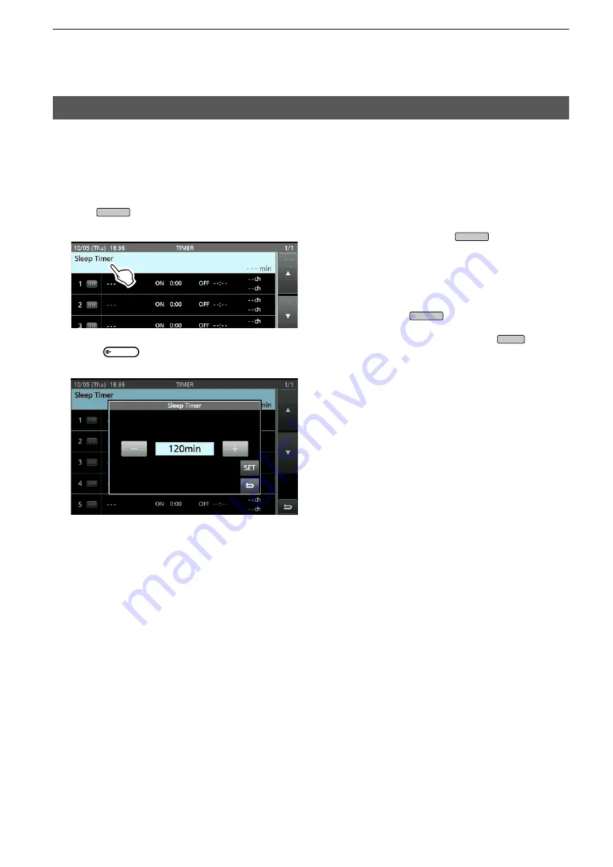
Setting the Sleep Timer

The Sleep Timer automatically turns OFF the 
transceiver power when the set time period has 
passed. You can set the timer to between 5 and 120 
minutes, in 5 minute steps.

1.  Push 

TIMER

 for 1 second.

2.  Touch “Sleep Timer.”

3.   Rotate 

MULTI

 to set the sleep timer.  

(Example: 120 minutes)

4.   Touch [SET] to save the setting and to start the 

timer.


• The timer indicator on the 

TIMER

 key turns ON.


•  Approximately 10 seconds before the transceiver 

power turns OFF, the indicator on the key starts 
blinking.

L

 After the transceiver turns OFF, the Sleep Timer set 
in step 3 is cleared.

L

 To pause and resume the timer while the timer is 
running, push 

TIMER

.

5.   To close the TIMER screen, push 

EXIT

.

Содержание IC-7610

Страница 1: ...RATION 6 SD CARD USB FLASH DRIVE ADVANCED 5 VOICE TX MEMORY OPERATION 4 VOICE RECORDER FUNCTIONS 3 ADVANCED SCOPE OPERATION 2 ADVANCED OPERATIONS 1 ADVANCED CONNECTIONS INTRODUCTION Instructions for advanced operations and additional details are described in this manual See the Basic manual for the basic operations especially for new users i7610 HF 50 MHz TRANSCEIVER ...

Страница 2: ...peater input signal 34 Tone squelch operation 35 Data mode AFSK operation 36 Transverter operation 36 Transverter setting example 36 About the 5 MHz frequency band operation 37 3 ADVANCED SCOPE OPERATION 36 Spectrum Scope screen 36 Center mode 36 Fixed mode 36 Directly tuning to a signal 37 Dual Scope screen 37 Sweep speed 38 Adjusting the Reference level 38 SCOPE SET screen 39 4 VOICE RECORDER FU...

Страница 3: ...on 66 Squelch status 66 SCAN screen 67 SCAN SET screen 67 Programmed scan 68 Programmed scan operation 68 Memory scan 69 Memory scan operation 69 Setting the Select Memory channels 69 Memory scan operation 70 F scan 71 F scan operation 71 9 CLOCK AND TIMERS ADVANCED 72 NTP function 72 Using the NTP Time Synchronize function 72 Using the NTP function 72 Setting the Timers 73 Setting the Sleep Timer...

Страница 4: ...or search screen or advanced search screen Printing out the desired pages Click Print in File menu and then select the paper size and page numbers you want to print The printing setup may differ depending on the printer Refer to your printer s instruction manual for details Select A4 size to print out the page in the equalized size Read Out Loud feature The Read Out Loud feature reads aloud the te...

Страница 5: ... the Transverter Function item to ON or connect a DC voltage to ACC 2 6 TRV 1 137 kHz band operation European version only ANT Amplifier Coaxial cable 50 Ω SEND SEND GND X VERTER 1 GND RX ANT TX TX RX RF IN OUT PA BPF LPF MENU SET Function Transverter Function Set the offset frequency in the Transverter Offset item to 0 000 MHz to match the transceiver s operating frequency and the transmitting fr...

Страница 6: ...itting LINK LED Lights while the RC 28 is connected to the transceiver Main dial Changes the Sub band s operating frequency with the default setting F 1 F 2 LEDs F1 lights when operating the Main band and F 2 lights when operating the Sub band F 1 F 2 buttons Selects the Main band or Sub band to operate with the main dial TRANSMIT button Push to switch between transmit and receive The F 1 and F 2 ...

Страница 7: ...ld index html Support Firmware Updates Software Downloads Transceiver When using the ACC socket or the microphone connector C E B RTS GND D Sub 25 D Sub 9 C E B TXD A B C D E 1 2 3 4 5 6 7 8 B F E D C 8 2 7 6 1 3 5 4 A B C D E Connecting to ACC 1 Connecting to MIC Shield cable ACC Connect to C MIC Connect to F Shield cable Shield cable Shield cable Shield cable Connect to LINE IN or MIC IN No conn...

Страница 8: ...ers the 2 5 to 30 MHz range with a supplied whip antenna Or when using with the optional NVIS kit it covers the 2 2 to 30 MHz range LSee the AH 740 instruction manual for installation and connection details AH 740 TUNER ANT 1 GND GND OPC 2321 Rubber vulcanizing tape then electrical tape Coaxial cable OPC 2321 Ground strap Vehicle chassis or body Coaxial cable and control cable connections ...

Страница 9: ...SET Function Band Edge Beep 1 Open the Band Edge Beep screen MENU SET Function Band Edge Beep 2 Select ON User or ON User TX Limit LIf you select ON User TX Limit you can limit transmission to within the entered frequency range 3 Select User Band Edge The User Band Edge screen is displayed 4 Touch ENT to save the edited lower band edge frequency Editing a Band Edge You can edit a band edge that is...

Страница 10: ...edge will be cleared when you push ENT Inserting a Band Edge After you edit the preset band edges follow the steps below to insert a band edge 1 Display the User Band Edge screen 2 Touch the band edge you want to insert a new band edge above for 1 second Example 1 3 500 000 3 999 999 MHz LThe new band edge will be inserted above the selected band edge 3 Touch Insert 4 Enter the lower and upper ban...

Страница 11: ...d Edge on page 5 for details on entering the band edge frequencies 4 Touch ENT to save the entered band edge frequencies The entered band edge is saved and returns to the previous screen Deleting a Band Edge You can delete band edges doing the following steps 1 On the FUNCTION set screen select User Band Edge 2 Touch the band edge you want to delete for 1 second Example 1 1 800 000 1 999 999 MHz 3...

Страница 12: ... all the band edges to their initial settings All entered settings will be deleted 1 Display the User Band Edge screen 2 Touch any band edge for 1 second 3 Touch Default Displays Reset All Edges 4 Touch YES All the band edges will be reset to the initial settings Band Edge Beep continued ...

Страница 13: ...eading swings between 30 to 50 of the ALC scale when speaking into the microphone at your normal voice level or keying a CW key 6 Release PTT or push TRANSMIT Returns to receive IP Plus function The IP Plus function improves the Intermodulation Distortion IMD quality by optimizing the direct sampling system performance This function optimizes the Analog Digital Converter ADC against distortion whe...

Страница 14: ...mode are synchronized with the Main band s LWhen using the RC 28 if the offset frequency is set between the Main band and the Sub band the frequency changes with the offset amount when rotating MAIN DIAL 4 Hold down MAIN SUB for 1 second to turn OFF the Tracking function The Tracking function will be canceled when Starting a scan Changing the operating band or directly entering the operating frequ...

Страница 15: ... VOX function 1 Set the operating mode to SSB AM or FM 2 Touch VOX to turn ON the VOX function VOX is displayed while the VOX function is ON VOX GAIN Default 50 Adjust the transmit receive switching threshold level to between 0 and 100 for VOX operation Higher values make the VOX function more sensitive to your voice ANTI VOX Default 50 Adjust the ANTI VOX level to between 0 and 100 to prevent unw...

Страница 16: ... set the TX frequency to match the receiving station s frequency LTo reset the TX frequency to 0 00 hold down CLEAR for 1 second LYou can add the frequency shift to the operating frequency by holding down TX for 1 second 3 To turn OFF the TX function push TX TX frequency Set the TX frequency While holding down XFC D TX monitor function When the TX function is ON you can directly monitor the operat...

Страница 17: ...the CW mode 2 Push TRANSMIT The TX RX indicator lights red LIf you want to automatically switch between transmit and receive turn ON the Break in function See Basic manual section 4 3 Touch a Memory Keyer key between M1 and M8 Example M1 The touched Memory Keyer is sent 4 To stop sending touch the Memory Keyer key again LThe Memory contents will be repeatedly sent according to the setting in Keyer...

Страница 18: ...he CW contest number If you want to set the Count up trigger to different keyer select other keyer in Keyer memory edit menu EDIT See Basic manual section 4 Using a USB keyboard or external keypad You can send the preset contents without opening the KEYER screen See Basic manual section 13 DKeyer memory edit menu EDIT Edit the Memory keyer contents in the EDIT menu LYou can use up to a total of 8 ...

Страница 19: ...ET You can set the number style count up trigger and preset number Setting 1 Display the KEYER 001 menu in the CW mode MENU KEYER EDIT SET 001 SET 2 Select the setting item Example Number Style 3 Select the setting option Returns to the KEYER 001 menu 4 To close the Number Style screen push EXIT several times TIP How to reset to the default setting Touching the item or its option for 1 second disp...

Страница 20: ...ds LAfter transmitting a Memory keyer the transmission is repeated after the set time period L is displayed even between transmissions Dot Dash Ratio Default 1 1 3 0 Set the dot dash ratio Set to between 1 1 2 8 1 1 4 5 in 0 1 steps Keying weight example Morse code K 1 1 3 1 1 2 8 4 5 Default 1 1 3 Setting range 1 1 2 8 to 1 1 4 5 Dash Dash Dot Setting range Space TX RX 0 Key action TX output powe...

Страница 21: ...he Hold function is ON this clears the characters and cancels the Hold function TX MEM Opens the RTTY MEMORY screen ADJ Opens the THRESHOLD screen You can adjust the threshold level Checking the RTTY DECODE rotate MAIN DIAL to adjust the threshold level to where the characters are not displayed by noise DEF Touch 1 sec Resets the Threshold level to the default LThe DEF key is displayed when after ...

Страница 22: ... displays the received signal strength when a signal is received If you are receiving an RTTY signal but cannot decode correctly try in the RTTY R reverse mode BFO BFO 170 Hz 2125 Hz 170 Hz 2125 Hz RTTY mode Normal RTTY R mode Space Mark Space Mark TIP If you cannot receive change the settings for RTTY Mark Frequency and RTTY Shift Width MENU SET Function RTTY Mark Frequency MENU SET Function RTTY...

Страница 23: ...memory between RT1 and RT8 to transmit Example RT1 Transmitting contents are displayed Lights red The TX status indicator lights red and the Po meter swings LTo cancel the transmission and to return to the RTTY DECODE screen push EXIT LAfter transmitting automatically returns to receive When a keyboard is connected You can transmit the preset contents in the RTTY memory RT1 RT8 by pushing F1 F8 on...

Страница 24: ...its the selected memory and returns to receive AUTO TX Automatically transmits the selected memory and then returns to receive by pushing F12 on the keyboard AUTO RX The selected memory contents are displayed on the RTTY DECODE screen Push F12 on the keyboard to transmit the selected memory and then it automatically returns to receive after transmission 1 Display the RTTY DECODE screen MENU DECODE...

Страница 25: ...p to 70 characters 1 Display the RTTY MEMORY editing screen LYou can also push QUICK and then touch Edit Memory Content 3 To clear a character touch or to move the cursor then touch CLR 4 Enter the new characters and then touch ENT to save 5 To exit the RTTY DECODE screen push EXIT several times Operating RTTY FSK Continued 2 Touch the memory to edit the content Example RT2 MENU DECODE TX MEM EDIT...

Страница 26: ...RTTY DECODE LOG screen MENU DECODE MENU1 LOG 2 Touch Decode Log 3 Select ON 4 Push EXIT is displayed on the RTTY DECODE screen while the RTTY log is ON 5 To turn OFF the RTTY log select OFF in step 3 Log Set File Type Default Text Set the ile type to save a log onto an SD card to Text or HTML LYou cannot change the ile type while logging TIP How to reset to the default setting Touching the item or...

Страница 27: ...t an item from File Information Delete and Delete All File Information Displays the ile name size and logged date Delete Deletes the selected log ile Delete All Deletes all log iles DRTTY Decode Log set This mode is for the log ile type time stamp setting and other RTTY settings 1 Display the RTTY DECODE SET screen MENU DECODE MENU1 SET 2 Select an item to set Example FFT Scope Averaging 3 Select ...

Страница 28: ...GS character even though it is not required by the receiving station ON Inserts FIGS OFF Does not insert FIGS Auto CR LF by TX Default ON Selects whether or not to automatically send a new line code CR LF when transmitting ON Transmits a CR LF code OFF Does not transmit the CR LF code Time Stamp Default ON Select whether or not display the time stamp date transmission time and reception time on th...

Страница 29: ... 31 63 Toggles between the BPSK31 and BPSK63 modes LOG Displays the PSK DECODE LOG set screen Starts Stops saving a log ile or sets the ile type LOG VIEW Displays the PSK DECODE LOG VIEW screen You can view the saved log contents SET Displays the PSK DECODE SET screen DDisplaying the PSK DECODE screen With the built in demodulator and decoder received PSK signals are displayed on the PSK DECODE sc...

Страница 30: ...ved signal is not properly demodulated try selecting the PSK R mode In the QPSK mode the phase shift direction must be the same on both the transmit and receive sides To receive the reverse direction signal select the PSK R mode to match the phase shift direction to the transmit side MENU SET Function PSK Tone Frequency DAFC NET function The IC 7610 has an AFC Auto Frequency Control function which...

Страница 31: ... between PT1 and PT8 to transmit Example PT1 The TX status indicator lights red and the Po meter swings LTo cancel the transmission and to return to the PSK DECODE screen push EXIT LAfter transmitting automatically returns to receive When a keyboard is connected You can transmit the preset contents in the PSK memory PT1 PT8 by pushing F1 F8 on the USB keyboard After transmitting the preset content...

Страница 32: ...its the selected memory and returns to receive AUTO TX Automatically transmits the selected memory and then returns to receive by pushing F12 on the keyboard AUTO RX The selected memory contents are displayed on the PSK DECODE screen Push F12 on the keyboard to transmit the selected memory and then it automatically returns to receive after transmitting 1 Display the PSK DECODE screen MENU DECODE L...

Страница 33: ... up to 70 characters 1 Display the PSK MEMORY editing screen LYou can also push QUICK and then touch Edit Memory Content 3 To clear a character touch or to move the cursor then touch CLR 4 Enter the new characters and then touch ENT to save 5 To exit the PSK DECODE screen push EXIT several times 2 Touch the editing memory content Example PT2 MENU DECODE TX MEM EDIT Operating PSK Continued ...

Страница 34: ...ENU DECODE MENU2 LOG 2 Touch Decode Log 3 Select ON 4 Push EXIT is displayed on the PSK DECODE screen while the PSK log is ON 5 To turn OFF the PSK log select OFF in step 3 Log Set File Type Default Text Set the ile type to save a log onto an SD card to Text or HTML LYou cannot change the ile type while logging TIP How to reset to the default setting Touching the item or its option for 1 second di...

Страница 35: ...ation Delete and Delete All File Information Displays the ile name size and logged date Delete Deletes the selected log ile Delete All Deletes all log iles DPSK Decode Log set This mode is for the log ile type time stamp setting and other PSK settings 1 Display the PSK DECODE SET screen MENU DECODE MENU1 SET 2 Select an item to set Example FFT Scope Averaging 3 Select a setting option Example 2 LS...

Страница 36: ...E screen and add it in the log OFF Does not display or add the time stamp ON Displays and adds the time stamp in the log Time Stamp Time Default Local Select whether or not to display the log on the PSK DECODE screen and to save it with the local time or with the UTC time when Time Stamp is ON Local Displays and saves in the local time UTC Displays and saves in UTC time Time Stamp Frequency Defaul...

Страница 37: ... frequency Split function ON Repeater Tone ON MENU SET Function SPLIT FM SPLIT Offset HF LYou can set the frequency offset for the 50 MHz MENU SET Function SPLIT FM SPLIT Offset 50M DSetting the repeater tone frequency Some repeaters require a subaudible tone in order to be accessed Subaudible tones are superimposed on your signal and must be set irst Do the following steps to set the tone frequen...

Страница 38: ...ter is received 2 To close the TONE FREQUENCY screen push EXIT D Settingtherepeatertonefrequency Continued Blinks while scanning DChecking the repeater input signal You can check whether you can directly receive another station s transmit signal or not by listening to the repeater input frequency LWhile receiving hold down XFC to listen the repeater input frequency LWhile listening the TX RX indic...

Страница 39: ...e frequencies 67 0 88 5 114 8 151 4 177 3 203 5 250 3 69 3 91 5 118 8 156 7 179 9 206 5 254 1 71 9 94 8 123 0 159 8 183 5 210 7 74 4 97 4 127 3 162 2 186 2 218 1 77 0 100 0 131 8 165 5 189 9 225 7 79 7 103 5 136 5 167 9 192 8 229 1 82 5 107 2 141 3 171 3 196 6 233 6 85 4 110 9 146 2 173 8 199 5 241 8 Checking another station s tone frequency You can check another station s tone frequency by tone s...

Страница 40: ... Transverter operation You can use the Transverter function as an exciter for a transverter DTransverter setting example This is an example of operating a 144 MHz band transverter using the IC 7610 s 50 MHz band 1 Connect the 144 MHz band transverter s RF output to X VERTER 2 Set the operating band and mode Example 50 MHz band MAIN SSB 3 Rotate MAIN DIAL to set the frequency Example 50 000 00 4 Tu...

Страница 41: ...FCC transmission is illegal on any frequencies other than the ive shown in the tables below For the USB and USB data modes The FCC speciies center frequencies on the 5 MHz frequency band However the transceiver displays carrier frequency Therefore tune the transceiver to 1 5 kHz below the speciied FCC channel center frequency Transceiver displayed frequency FCC channel center frequency 5 33050 MHz...

Страница 42: ...ransceiver 1 Display the SPECTRUM SCOPE screen 4 To close the SPECTRUM SCOPE screen push EXIT MENU SCOPE Center mode is selected 2 5 kHz 2 5 kHz MENU SCOPE 2 Touch CENT FIX to select the Fixed mode LTouch CENT FIX to toggle between the Center and Fixed modes 3 Touch EDGE several times until the desired Fixed Edge frequency band is selected LThe ixed Edge frequencies are settable p 41 Fixed mode is...

Страница 43: ...the cursor the frequency changes Release to return to the originally selected frequency By clicking and dragging with the cursor the frequency changes to that where the cursor is released 4 To exit the SPECTRUM SCOPE screen push EXIT DDisplaying the Dual Scope screen The transceiver has a Dual scope mode that simultaneously displays the Main and Sub band scopes during Dualwatch operation 1 Display...

Страница 44: ...ng the Reference level When monitoring a weak signal that is buried in the noise loor or monitoring a strong signal but some stronger signals are nearby adjusting the Reference level of the screen helps you to see these signals Even if this setting is changed it does not affect the input signal level When you adjust the Reference level the signal strength for the waterfall also appears to change 1...

Страница 45: ...Only in the Center mode Filter Center Displays the selected ilter s center frequency in the center of the SPECTRUM SCOPE screen Carrier Point Center Displays the carrier point frequency of the selected operating mode in the center of the SPECTRUM SCOPE screen Carrier Point Center Abs Freq In addition to the carrier point center setting above the actual frequency is displayed at the bottom of the s...

Страница 46: ...low Mid Sets the waterfall speed to Mid Fast Sets the waterfall speed to Fast Waterfall Size Expand Screen Default Mid Select the Waterfall height in the Expand scope screen Small The same height as the Normal scope screen only the FFT scope expands Mid The Waterfall height expands at the same ratio as the FFT scope Large Only the Waterfall height expands SCOPE SET screen Continued Waterfall Peak ...

Страница 47: ...4 350 MHz Default No 2 14 000 14 100 MHz Default No 3 14 100 14 350 MHz Settable range 11 000 15 000 MHz 15 00 20 00 Default No 1 18 068 18 168 MHz Default No 2 18 068 18 110 MHz Default No 3 18 110 18 168 MHz Settable range 15 000 20 000 MHz 20 00 22 00 Default No 1 21 000 21 450 MHz Default No 2 21 000 21 150 MHz Default No 3 21 150 21 450 MHz Settable range 20 000 22 000 MHz 22 00 26 00 Default...

Страница 48: ... ile When the PTT Automatic Recording function PTT Auto REC is set to ON in RECORDER SET the recording automatically starts when you start transmitting REC QUICK MENU There are 3 ways to start recording z Hold down REC for 1 second z Push QUICK and select REC Start z Push MENU and touch RECORD LThe recorded audio is saved in the Voice folder on the SD card TIP About the icons While recording is di...

Страница 49: ... Select the file to play back Starts a playback L Playback continues to the next ile and stops when the last ile in the folder is played back 5 To close the PLAY FILES screen push EXIT several times Recording start time and date The number of ile The TX RX status of the recorded audio Play back icon Play back time Total time Play back process Operating frequency operating mode of the Main and Sub ...

Страница 50: ...ils When the ile does not playback after double clicking the ile download an appropriate software Example Windows Media Player LO CK SD SD card Memory card reader PC 2 Open the Voice folder 3 Open the folder where the file you want to playback is saved LThe folders are titled based on the recorded date yyyymmdd IC 7610 Capture Decode Psk yyyymmdd yyyymmdd Rtty Setting Voice VoiceTx 4 Double click ...

Страница 51: ...RD Play Files 2 Touch a folder for 1 second 3 Touch Folder Information The FOLDER INFORMATION screen is displayed 4 To close the PLAY FILES screen push EXIT several times Checking the ile information 1 Display the PLAY FILES screen MENU RECORD Play Files 2 Touch a folder 3 Touch a file to check its information for 1 second The QUICK MENU is displayed 4 Touch File Information The FILE INFORMATION s...

Страница 52: ...ll Delete File is displayed 5 Touch YES The ile is deleted and returns to the previous screen 6 To close the PLAY FILES screen push EXIT several times Deleting folders 1 Display the PLAY FILES screen MENU RECORD Play Files 2 Touch the folder you want to delete for 1 second The QUICK MENU is displayed 3 Touch Delete LIf you want to delete all folders touch Delete All Folders Delete Folder is displa...

Страница 53: ...ated in the same folder and the audio is saved into the new one PTT Auto REC Default OFF Turns the PTT Automatic Recording function ON or OFF OFF The recording does not start even if a signal is transmitted ON The recording automatically starts when a signal is transmitted The recording will stop when 10 seconds has passed without transmission after the last transmission 10 minutes has passed with...

Страница 54: ... screen 1 Display the PLAYER SET screen PLAYER SET screen MENU RECORD Player Set 2 Touch Skip Time 3 Touch an option Example 5 seconds 4 To close the PLAYER SET screen push EXIT TIP How to reset to the default setting Touching the item or its option for 1 second displays the Quick menu and then touch Default to reset to the default setting ...

Страница 55: ...How to reset to the default setting Touching the item or its option for 1 second displays the Quick menu and then touch Default to reset to the default setting DRecording the Instant Replay The Instant Replay function records the previous 15 seconds default from the time when REC has been pushed The audio is recorded into the built in memory LYou can only record once and the memory is overwritten ...

Страница 56: ...ng down PTT to start recording Information L You can record up to one and a half minutes in each memory The previously recorded content is overwritten 6 Touch to stop recording 7 To close the VOICE TX screen push EXIT several times TIP How to clear the recorded content Touch the Voice memory for 1 second in step 4 to display the Quick menu and then touch Clear 4 Touch of the TX memory Example T1 3...

Страница 57: ...nter the name for 1 second LThe selected memory needs to contain a recording Opens the QUICK MENU screen 3 Touch Edit Name Opens the Name editing screen 4 Enter a name and then touch ENT to save The editing screen closes and returns to the VOICE TX RECORD screen The entered name is displayed 5 To close the VOICE TX RECORD screen push EXIT LThe entered memory name is also displayed on the VOICE TX ...

Страница 58: ...een push EXIT The transmission s remaining time Transmitting The SD card indicator next to the card slot blinks while transmitting When a keyboard or keypad is connected You can transmit the preset contents in the Voice TX memory T1 T8 by pushing F1 F8 on the keyboard Pushing F1 F8 while holding down the Shift key repeatedly transmits the contents MENU SET Connectors Keyboard Mouse Keyboard F1 F8 ...

Страница 59: ...et to open the transceiver repeatedly transmits after the repeat interval time expires even signals are received 3 To close the VOICE TX screen push EXIT DRepeatedly transmitting 1 Display the VOICE TX screen MENU VOICE 2 Touch a Voice TX memory key T1 T8 for 1 second Repeatedly transmits the recorded content The transmission s remaining time Repeat icon Transmitting The SD card indicator located ...

Страница 60: ...transmits the recorded content for up to 10 minutes LAfter 10 minutes have passed and all of the recorded content in the memory is transmitted the transceiver automatically returns to receive This set screen is used to set the Automatic Monitor function and the Transmit Repeat Interval 1 Display the VOICE TX SET screen MENU VOICE REC SET SET 2 Touch the setting item Example Auto Monitor TIP How to...

Страница 61: ... MENU SET USB Flash Drive Save Setting 3 Touch New File LThe ile name is automatically set in the following format Setyyyymmdd_xx yyyy Year mm month dd day xx serial number TIP When you have updated the transceiver s irmware the Save Form item will be added on the setting screen If this item is set to the earlier irmware version the conirmation window is displayed after step 3 To save the data in ...

Страница 62: ...U SET SD Card Load Setting MENU SET USB Flash Drive Load Setting 2 Touch the file to load 3 Touch Select LIf you want to load all the contents on the LOAD OPTION screen touch ALL and go to step 6 4 Touch the loading options Example Antenna Memory is displayed left side of the selected option LThe Set mode settings and Memory channel contents are always loaded 5 Touch Load Load ile is displayed 6 T...

Страница 63: ...our PC 1 Display the SAVE SETTING screen MENU SET SD Card Save Setting MENU SET USB Flash Drive Save Setting 2 Touch the file to delete for 1 second Deleting a data ile 3 Touch Delete Delete ile is displayed LTo delete all iles touch Delete All LTo cancel deleting push EXIT 4 Touch YES 5 To close the SET screen push EXIT several times Checking the ile information Touch File Information on the QUIC...

Страница 64: ...SD card only 1 Display the SD CARD or USB FLASH DRIVE screen MENU SET SD Card MENU SET USB Flash Drive 2 Touch SD Card Info or USB Flash Drive info Example SD Card Info Displays the card or lash drive s free space and the capacity Displaying the SD card or USB lash drive information 3 To close the SET screen push EXIT several times ...

Страница 65: ...ecode log folders are created z PSK folder The transmitted or received PSK decode log data is saved in the txt or html format z RTTY folder The transmitted or received RTTY decode log data is saved in the txt or html format z Setting folder The transceiver s setting data is saved in the dat format z Voice folder The recorded QSO audio date folders are created z yyyymmdd folder Recorded audio iles ...

Страница 66: ...nnel P1 P2 Scan Edge memory channels 1 frequency and 1 mode and 1 ilter in each memory channel as scan edges for programmed scans Selecting a Memory channel 1 Select the Main band or Sub band Example Main band 2 Push QUICK and then touch VFO MEMORY on the Quick menu 3 Touch MEMORY to select the Memory mode Memory mode Example Memory channel 1 4 Select the Memory channel Rotating MULTI to select a ...

Страница 67: ...e screen expanded screen or dual screen is displayed LIf is displayed next to the selected memory channel number it is a blank channel meaning that no contents are entered in that channel The channel is blank 5 Push QUICK and then touch VFO MEMORY 6 Touch MW for 1 second The contents are entered in the selected Memory channel The entered contents are displayed LTo enter another channel with the sa...

Страница 68: ... mode contents after copy 14 200 00 USB 5 Touch VFO to select the VFO mode 6 To close the VFO MEMORY screen push EXIT DCopying to the other Memory channel 1 Select the Main band or Sub band Example Main band 2 Select the Memory mode 3 Rotate MULTI to select the channel to be copied Example Memory channel 3 Select the channel to be copied 4 Display the MEMORY screen MENU MEMORY 5 Rotate MULTI to se...

Страница 69: ...NU MEMORY 2 Rotate MULTI to select the channel to enter a name Example Memory channel 2 3 Touch of the selected channel 4 Touch Edit Name 5 Enter a name and then touch ENT Example 1DX Spot Memory name 6 To close the MEMORY screen push EXIT Memory name LThe Memory name is not displayed when the Mini scope screen or expanded screen is displayed LYou can also select not to display the Memory name on ...

Страница 70: ...ry channels Memory select icon Touch this icon to set the select number 1 2 3 or OFF LYou can also touch the icon for 1 second to display the SELECT ALL CLEAR screen and then select the item to reset the select number w Frequency Operating mode IF ilter Displays the entered frequency selected operating mode and the IF ilter e Memory name Displays the memory name if entered LSee the previous for de...

Страница 71: ...4 Push MP W to save the displayed content A beep sounds LTo save additional Pads repeat steps 1 to 4 L When you save up to the set number of Memo Pads in Memo Pad Quantity the oldest Memo Pad is automatically cleared to make room for the new Memo Pad DCalling up the Memo Pads 1 Select the Main band or Sub band Example Main band 2 Push MP R LPushing MP R scrolls through the contents saved in the Me...

Страница 72: ...ration DSquelch status Scans work with the Main band s squelch status Be sure to adjust the squelch level according to your operating environment LNormally set AF RF SQL to the point where noise disappears and the TX RX indicator goes OFF When the scan starts with the squelch open For a Programmed scan When the tuning step is 1 kHz or less the scan continues until it is manually stopped it does no...

Страница 73: ...LECT Touch Selects a Memory channel to set as a Select Memory channel 1 2 3 and no icon are alternately displayed Touch 1 second Displays the SELECT ALL CLEAR screen SEL No Selects the Select scan number for the Select Memory scan Each time you touch SEL No 1 2 3 and 1 2 3 are alternately displayed SCAN SET screen 1 Display the SCAN screen MENU SCAN 2 Touch SET 3 Touch an item to set Example SCAN ...

Страница 74: ...ot start LThe Fine Programmed scan is most effective in the SSB CW and RTTY modes DProgrammed scan operation 1 Select the VFO mode in the Main band 2 Select the operating mode example USB tuning step 1 kHz 3 Display the SCAN screen MENU SCAN 4 Touch PROG to start the Programmed scan L PROGRAM SCAN blinks while scanning LYou can change the operating mode and the tuning step while scanning Frequency...

Страница 75: ... 1 Ch 5 1 Ch 4 1 Ch 3 1 Ch 50 3 Ch 98 1 Ch 99 1 1 2 and 3 show that the channel is specified as a Select Memory Example Select Memory channel 1 Repeatedly scans all or one of 3 Select Memory channels 1 2 3 LIf two or more Memory channels are not designated as Select Memory channels the Select Memory scan does not start DSetting the Select Memory channels 1 Select the Main band 2 Display the SCAN s...

Страница 76: ...eciied as 1 are scanned 2 Channels speciied as 2 are scanned 3 Channels speciied as 3 are scanned 1 2 3 Channels speciied as 1 2 or 3 are scanned 5 Touch SELECT to switch to the Select Memory scan LTouching SELECT switches between the Memory scan and the Select Memory scan Select Memory scan Blinks Select the Select Memory scan number Example 1 Blinks Memory scan 6 To cancel the scan touch MEMO 7 ...

Страница 77: ...Example USB 1 kHz LYou can also change these settings while scanning 3 Display the SCAN screen MENU SCAN 4 Touch F SPAN to select the span Options 5 kHz 10 kHz 20 kHz 50 kHz 100 kHz 500 kHz or 1 MHz 5 Touch F to start the scan LWhen a signal is detected the scan pauses according to the SCAN Resume setting and then resumes LTo cancel the scan touch F again LTo turn the TS function to scan by the fr...

Страница 78: ...e wait is displayed The transceiver starts accessing the NTP server address that is set in the NTP Server Address item 3 When Time Sync completed is displayed touch OK 4 To close the DATE TIME screen push EXIT several times MENU SET Time Set Date Time DUsing the NTP function By turning ON the NTP function the transceiver automatically synchronizes the internal clock with the time management server...

Страница 79: ...nd 2 Touch Sleep Timer 3 Rotate MULTI to set the sleep timer Example 120 minutes 4 Touch SET to save the setting and to start the timer The timer indicator on the TIMER key turns ON Approximately 10 seconds before the transceiver power turns OFF the indicator on the key starts blinking LAfter the transceiver turns OFF the Sleep Timer set in step 3 is cleared LTo pause and resume the timer while th...

Страница 80: ...e 1 3 Rotate MULTI scroll through the setting items and then touch an item to select LEach setting items are described on the next page LYou can reset to the default setting or cancel the setting by pushing QUICK 4 After setting the items touch Set to save them Timer Status Day of the Week Repeat Setting Reservation Timer Power OFF Timer Reservation Channel MAIN SUB Setting the Timers Continued 5 ...

Страница 81: ...ervation Timer 8 00 Power OFF Timer 9 30 Reservation Channel MAIN Default ch Reservation Channel SUB Default ch The Memory channel set in this item is automatically selected when the transceiver is automatically turned ON by the Reservation Timer or the set time has come while the transceiver is turned ON LYou cannot select a blank channel LTo clear the setting push QUICK and touch Clear Day of th...

Страница 82: ...e Main band and then you set RX I O to the Sub band the previous Main band setting is forcibly cleared and is displayed Setting Main back to RX IO SUB is forcibly cleared and is displayed RX I O is set to ANT1 ANT2 is selected RX I O is set to ANT2 RX I O is set RX I O is forcibly turned OFF The Main and Sub bands are not forcibly set or cleared when the RX ANT Connectors Type is set to Connect Re...

Страница 83: ...h ANT for 1 second to set the antenna that is connected to ANT2 for transmitting and the antenna connected to RX ANT IN for receiving is displayed if you temporarily select an antenna that is different from the one that is saved in the memory Touch ANT MW for 1 second to save the temporary selection into memory then disappears When the antenna selection mode ANT SW is set to Manual each antenna co...

Страница 84: ...uits for the Main and Sub bands from the antenna to the AF output RF signals are directly converted to digital data and processed in the Field Programmable Gate Array FPGA This system is a leading technology marking an epoch in amateur radio FPGA D A A D A D D A Demodulation circuit BPF BPF DIGI SEL ANT 1 EXT SP A EXT SP B ANT 2 Main band Sub band DIGI SEL ...

Страница 85: ...noise squelch or S meter squelch Noise squelch FM mode S meter squelch threshold S meter squelch adjustable range Maximum S meter squelch Squelch is open Noise squelch threshold When using as an RF gain squelch control When using as an RF gain control Squelch is ixed open SSB CW RTTY PSK only When using as a squelch control RF gain is ixed at maximum Noise squelch FM mode S meter squelch adjustabl...

Страница 86: ... B RTS Uses the RTS terminal on USB1 B The IC 7610 has two virtual COM ports A and B When connecting to a USB port on your PC the ports are virtually named as USB1 A and USB1 B and then the transmit and receive control USB SEND CW Keying or RTTY FSK Keying signals from the PC are assigned to the DTR RTS terminals in the virtual port TIP About the USB SEND Keying items LWhen you operate RTTY or CW ...

Страница 87: ...e meter indicator for 1 second SWR meter display 4 Select the antenna connector that the antenna that you want to measure is connected to 5 Push MULTI to adjust the RF POWER to more than 30 W in the Multi function menu Before transmitting monitor the operating frequency to make sure you will not cause interference to other stations on the same frequency 6 Hold down PTT or push TRANSMIT to transmit...

Страница 88: ...ng the Display Font You can select between 2 frequency readout fonts 1 Display the DISPLAY screen MENU SET Display 2 Touch Display Font 3 Select the display font type from Basic and Round Basic default Round 4 To close the DISPLAY screen push EXIT Displaying my call sign You can set to display your own call sign at power ON Example displaying the call sign JA3YUA 1 Display the DISPLAY screen MENU ...

Страница 89: ...APTURE VIEW screen push QUICK 3 To close the SD CARD or USB FLASH DRIVE screen push EXIT several times Screen Capture function You can capture the transceiver display onto an SD card or a USB lash drive Most of the screens used in this manual are captured using this function However some screens cannot be captured DSetting the Screen Capture function 1 Display the Screen Capture POWER Switch scree...

Страница 90: ...below Operating mode USB AF RF SQL Decent audibility AF RF SQL Maximum RF gain TWIN PBT CLR Reset by holding down for 1 second RIT TX OFF No icon 1 Set the frequency to the standard frequency station minus 1 kHz LIf receiving WWV or WWVH at 15 00000 MHz as your standard frequency set the operating frequency to 14 99900 MHz 2 Set Calibration Marker to ON MENU SET Function Calibration Marker 3 Selec...

Страница 91: ...e problem Then replace the damaged fuse with a new adequately rated fuse L Spare fuses are supplied with the transceiver The fuses are installed in the DC power cable and in the inside circuitry to protect the transceiver DC power cable fuses ATC 30 A Circuitry fuse ATC 5 A RWARNING Disconnect the DC power cable from the transceiver before replacing the fuse NEVER use fuses that are not speciied R...

Страница 92: ... the carrying handle if attached 2 Remove the 10 top cover screws then remove the cover 3 Remove the 15 shield screws then remove the shield cover 4 Replace the circuitry fuse as shown below ATC 5 A fuse 5 Replace the removed parts CAUTION When you remove a fuse use longnose pliers to protect your ingers and the fuse holders ...

Страница 93: ...o the following steps to display the Touch Screen Calibration screen 1 Turn OFF the transceiver 2 While holding down MENU and EXIT push POWER to display the Touch Screen Calibration screen 3 Repeat step 3 and 4 on the left column 4 Touch the frequency readout or a key on the touch screen to confirm that the touch screen is working correctly MENU Set Others 2 Touch Touch Screen Calibration A dot ap...

Страница 94: ...new functions and or improves performance parameters You can download the latest irmware from the Icom website http www icom co jp world index html DChecking the irmware version Check the irmware version when you turn ON the transceiver TIP You can also check the irmware version on the INFORMATION screen MENU SET Others Information The irmware version is displayed ...

Страница 95: ...ck Agree Click 5 Click Save as in the displayed File Download dialog Click 6 Select the location where you want to save the firmware and then click Save in the displayed File Download dialog The ile starts downloading The irmware and the irm utility are compressed in a zip format folder Unzip it before use Click DUnzipping the irmware folder 1 Right click the downloaded firmware folder zip format ...

Страница 96: ...repair This type of repair is out of warranty even if the transceiver warranty period is still valid TIP BE SURE to unzip the downloaded ile See the previous page for details 1 Copy the downloaded firmware data into the IC 7610 folder on an SD card or a USB flash drive Copy 2 Insert the SD card or USB flash drive into the transceiver 3 Display the SD CARD or USB FLASH DRIVE screen MENU SET SD Card...

Страница 97: ...it to the main CPU sub CPU front CPU and FPGA L Downloading and loading status are displayed in the dialogs 8 When the update is completed Firmware updating has completed is displayed in the dialog The IC 7610 will automatically restart L After the updating inishes the operating screen is displayed 6 After you read and agree with all the precautions touch YES for 1 second The updating starts ...

Страница 98: ...yer function KEYER 13 D Data mode AFSK operation 36 Display Font 82 Display Type 82 Drive Gain level Adjusting the Drive Gain level 9 F File Split 47 Firmware Checking the version 88 Updating 90 Firmware updating Preparation 89 FM repeater Checking the repeater input signal 34 Checking the repeater tone frequency 34 Setting the repeater tone frequency 33 FM repeater operation 33 FPGA 78 Fuse 85 Ci...

Страница 99: ...24 FFT Scope Waveform Color 24 Font Color 24 Time Stamp 24 Time Stamp Frequency 24 Time Stamp Time 24 TX USOS 24 RX REC Condition 47 S Scan 66 Fine F scan 66 71 Fine Programmed scan 66 F scan 66 71 Memory scan 66 69 Preparation 66 Programmed scan 66 68 Select Memory scan 66 69 Squelch status 66 VFO scan 66 SCAN Resume 67 SCAN screen 67 SCAN SET screen 67 SCAN Speed 67 Scope set screen 39 Averaging...

Страница 100: ...59 Information displaying 58 Loading 56 Saving 55 USB Keying CW 80 USB Keying RTTY 80 USB SEND 80 USB SEND Keying 80 V Voice Recorder function 42 Checking the ile information 45 Checking the folder information 45 Deleting iles 46 Deleting folders 46 Voice TX memory Adjusting the output level 53 Entering a name 51 Playing back 50 Recording 50 Repeatedly transmitting 53 Transmitting 52 VOICE TX SET ...

Страница 101: ...1 1 32 Kamiminami Hirano ku Osaka 547 0003 Japan A7380 2EX 2017 Icom Inc ...

Отзывы: