4
DR MODE <ADVANCED>
1
2
3
4
5
6
7
8
9
10
11
12
13
14
15
16
17
18
19
20
21
4-23
4. Repeater call sign programming
When used for simplex communication, go to
[7. Access repeater setting].
!7
Push D-pad(
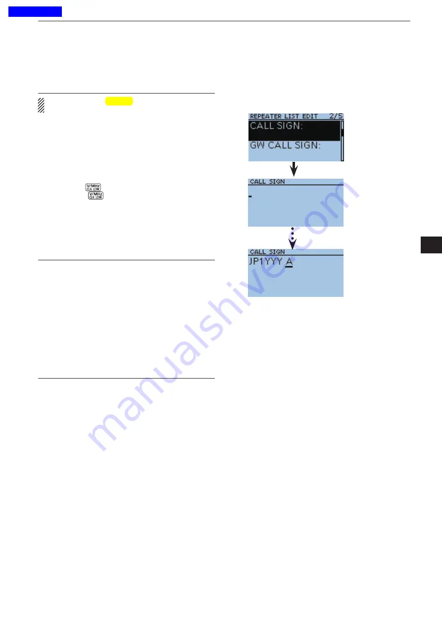
) to select “CALL SIGN,” and then
push D-pad(Ent) to enter the repeater call sign edit
mode.
!8
Rotate [DIAL] to select the first character.
• A to Z, 0 to 9, / and a space can be selected.
• A space can be selected, even for any input mode se
-
lected.
• Push [CLR]
to erase the selected character, or hold
down [CLR]
to continuously erase the characters
after the cursor.
!9
Push D-pad(
"
) to move the cursor to the second
digit.
@0
Repeat steps
!8
and
!9
to enter a name of up to 8
characters, including spaces.
@1
After entering the call sign, push D-pad(Ent).
Information
✓
Be sure to add a repeater node (port) letter as the 8th
digit in the call sign field after a repeater call sign, ac-
cording to the repeater frequency band, as shown be-
low.
Note that Japanese repeater node letters are differ-
ent.
1200 MHz : A (B in Japan)
430 MHz : B (A in Japan)
144 MHz : C (no D-STAR
®
repeaters in Japan)
Cross band operation between different nodes at the
same repeater site can be made.
☞
Continued on the next page.
Example:
“JP1YYY A” is
entered.
Previous view


