background image

ICE Series 


 Troubleshooting Trees 

Page C3 


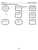
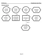
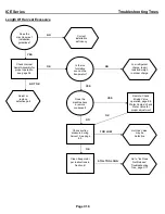
Machine Does Not Run 


Check for correct 

power supply to the 

machine 

YES 

NOT OK 

NO 

OK 


Is the selector 

switch set to 

ICE


Check High 

Pressure Safety 

Control 


Check High 

Temperature Safety 

Control 

OK 


Check Bin Control 

for proper 

adjustment, see 

page F9 


Is this a Remote 

unit? 


Is the Liquid line 

Solenoid energized 

and open? 

OK 

OK 

GOOD 

TRIPPED

OPEN 

BAD 

NO

NOT OK


OK


Adjust as 

required or 

replace if 

defective 

 
Replace or 
identify reason 
for being open. 


Reset and 

identify reason 

for high head 

pressure


Correct field 

wiring deficiency 


Set selector 

Switch to the 

ICE

 position 


Selector Switch 

could be 

defective, see 

page F1 


Find reason for 

non-activity or 

replace if 

defective 


Содержание 16

Страница 1: ...CE AND INSTALLATION MANUAL THE ICE SERIES CUBERS ICE0250 through ICE2100 SERIES Includes Undercounter and 22 Inch Series ICE O Matic 11100 East 45th Ave Denver Colorado 80239 Part Number 9081270 01 Date 1 08 ...

Страница 2: ...eaning and Sanitizing Instructions Page B1 B2 Winterizing Procedure Page B3 Cabinet Care Page B4 Troubleshooting Trees How to Use The Troubleshooting Trees Page C1 Troubleshooting Trees Table Of Contents Page C2 Troubleshooting Trees Page C3 C18 Water System Water Distribution And Components Page D1 D5 Refrigeration System Refrigeration Cycle And Components Page E1 Harvest Cycle Page E5 Remote Sys...

Страница 3: ...izing Instructions Page B1 B2 Winterizing Procedure Page B3 Cabinet Care Page B4 Troubleshooting Trees How to Use The Troubleshooting Trees Page C1 Troubleshooting Trees Table Of Contents Page C2 Troubleshooting Trees Page C3 C18 Water System Water Distribution And Components Page D1 D5 Refrigeration System Refrigeration Cycle And Components Page E1 Harvest Cycle Page E5 Remote System Page E5 E6 P...

Страница 4: ...t suspected of malfunctioning A detailed description of the operation and adjustments of the components as well as other service information is available in the pages that follow Section C Sections D E and F focus on a particular system in the ice machine water distribution system refrigeration system and it is important that these sections be used together with the Troubleshooting Trees in Sectio...

Страница 5: ...b ice cuber Stainless Steel Cabinet Serial Number Date Code The first letter in the serial number indicates the month and decade of manufacture The first digit in the serial number indicates the year of manufacture Example A0XX XXXXX Z is manufactured January 2000 A1XX XXXXX Z is manufactured January 2001 1990 1999 MONTH 2000 2004 M JANUARY A N FEBRUARY B P MARCH C Q APRIL D R MAY E S JUNE F T JUL...

Страница 6: ...wed by the Ice O Matic identifier and then a sequential number This is an entirely numerical serial number The new serial number will look like the example 0407 1280 010123 010123 is the serial identifier 1280 is the identifier Ice O Matic 0407 is the date code in YYMM format 2004 July The date code will change monthly and yearly to reflect the date of manufacture Large data plate will be placed o...

Страница 7: ...A 16 454 ICE0250 W3 115 60 1 284 129 6030 3 15 10 8 8 2 R404A 13 369 ICE0250 A4 115 60 1 253 115 6248 3 15 13 3 8 6 R404A 25 709 ICE0250 A T4 115 60 1 253 115 6248 3 15 13 3 8 6 R404A 25 709 ICE0250 W4 115 60 1 275 125 5855 3 15 10 8 8 2 R404A 13 369 ICE0320 A1 115 60 1 214 97 5910 3 15 13 8 9 0 R404A 18 510 ICE0320 W1 115 60 1 312 142 6195 3 15 10 9 8 3 R404A 15 425 ICE0320 A2 115 60 1 214 97 591...

Страница 8: ...0606 A T2 208 230 60 1 510 232 11293 3 15 11 7 8 2 R404A 24 680 ICE0606 W2 208 230 60 1 590 268 11473 3 15 9 5 7 3 R404A 18 510 ICE0606 R2 208 230 60 1 544 247 12269 3 15 13 0 8 7 R404A 160 4536 ICE0606 R3 208 230 60 1 543 247 12132 3 15 13 0 8 7 R404A 132 3742 ICE0606 A3 208 230 60 1 506 230 10566 3 15 11 5 7 9 R404A 24 680 ICE0606 A T3 208 230 60 1 506 230 10566 3 15 10 4 7 0 R404A 24 680 ICE060...

Страница 9: ...468 667 27152 3 30 22 3 15 7 R404A 400 11340 ICE1806 W3 208 230 60 1 1628 740 27687 3 30 22 0 16 9 R404A 37 1049 ICE1806 R3 208 230 60 1 1461 664 28110 3 30 27 7 20 1 R404A 272 7711 ICE1807 W1 208 230 60 3 1556 707 27146 4 15 10 7 7 8 R404A 42 1191 ICE1807 R1 208 230 60 3 1491 678 27966 4 15 15 5 10 3 R404A 400 11340 ICE1807 W2 208 230 60 3 1556 707 27146 4 15 10 7 7 8 R404A 35 992 ICE1807 R2 208 ...

Страница 10: ...ICE0605 A3 230 50 1 459 209 9523 3 16 8 7 6 7 R404A 22 624 ICE0605 W3 230 50 1 523 238 9684 3 16 6 8 5 4 R404A 14 397 ICE0605 R4 230 50 1 474 215 10138 3 16 9 9 6 3 R404A 132 3742 ICE0805 A1 230 50 1 615 280 13321 3 15 12 0 10 9 R404A 41 1162 ICE0805 W1 230 50 1 855 389 14382 3 15 9 2 10 9 R404A 29 822 ICE0805 R1 230 50 1 738 335 14474 3 15 13 0 10 9 R404A 240 6804 ICE0805 A2 230 50 1 615 280 1332...

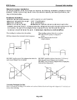
Страница 11: ... drain individually to a floor drain The use of condensate pumps for draining water is not recommended by Ice O Matic Ice O Matic assumes no responsibility for improperly installed equipment Water Filtration A water filter system should be installed with the ice machine Clearance Requirements Self contained air cooled ice machines must have a minimum of 6 inches 15cm of clearance at the rear top a...

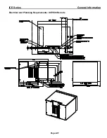
Страница 12: ...ICE Series General Information Page A10 Electrical and Plumbing Requirements ICEU150 ICEU220 ICEU205 and ICEU206 ...

Страница 13: ...on Page A11 Electrical and Plumbing Requirements ICEU150 220 225 and 226 Note The ICEU150 ICEU220 ICEU225 and ICEU226 do not have a splash curtain These models utilize a thermostatic bin control in place of a mechanical bin switch ...

Страница 14: ...eneral Information Page A12 Electrical and Plumbing Requirements ICEU300 and 305 305 Note The ICEU300 does not have a splash curtain This model utilize a thermostatic bin control in place of a mechanical bin switch ...

Страница 15: ...ICE Series General Information Page A13 Electrical and Plumbing Requirements ICE0250 ICE0400 ICE0500 ICE0606 ICE0806 and ICE1006 30 Inch Wide Cubers ...

Страница 16: ...ICE Series General Information Page A14 Electrical and Plumbing Requirements ICE1406 ICE1806 ICE2106 48 Inch Wide Cubers Prior to January 2008 ...

Страница 17: ...ICE Series General Information Page A15 Electrical and Plumbing Requirements ICE0320 and ICE0520 22 Inch Wide Cubers ...

Страница 18: ...ICE Series General Information Page A16 Electrical and Plumbing Requirements ICE1400 ICE1800 and ICE2100 Revision 3 From January 2008 ...

Страница 19: ...ICE Series General Information Page A17 Electrical and Plumbing Requirements ICE1506 Remote ...

Страница 20: ...elines Ambient operating temperatures 20 F 28 9 C to 120 F 48 9 C Maximum refrigerant line length 60 ft 18 29 Meters Maximum vertical rise 16 ft 4 88 Meters Minimum condenser height ICE Series ice machine remote condensers must not be installed more than 6 feet 1 3 meters below the refrigerant line quick connects at the rear of the ice machine No part of the refrigerant lines between the ice machi...

Страница 21: ...xing valve mounted in the condenser Maximum Rise is 35 feet Maximum Drop is 15 feet Maximum equivalent run is 100 feet Formula for figuring maximum equivalent run is as follows Rise x 1 7 Drop x 6 6 horizontal run equivalent run Examples 35 ft rise x 1 7 40 ft horizontal 99 5 equivalent feet line run 10 ft drop x 6 6 34 ft horizontal 100 equivalent feet line run 10 ft drop 34 ft horizontal 35 ft r...

Страница 22: ... and the machine will enter harvest Power is now supplied to the water purge valve hot gas valve and the harvest motor The water purge valve opens and allows the water pump to purge the water remaining in the water removing impurities and sediment This allows the machine to produce clear ice cubes and keep mineral build up at a minimum The hot gas solenoid opens allowing hot gas to go directly to ...

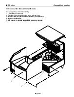
Страница 23: ...rill 2 Remove two screws securing bin to cabinet base 3 Remove the thumbscrews from the back wall of the bin 3 Remove the thumbscrews from the back wall of the bin 4 Disconnect bin drain 4 Disconnect bin drain 5 Lift front of bin slightly and pull bin forward to remove 5 Lift front of bin slightly and pull bin forward to remove 1 2 3 ...

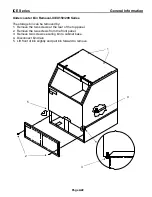
Страница 24: ...eries The storage bin can be removed by 1 Remove the two screws at the rear of the top panel 2 Remove the two screws from the front panel 3 Remove two screws securing bin to cabinet base 4 Disconnect bin drain 5 Lift front of bin slightly and pull bin forward to remove 5 4 3 2 1 ...

Страница 25: ...l IFQ and IFI filter systems Replacement filter must be model number IOMQ or IOMWFRC Available in the USA and Canada only Warranty If during the warranty period customer uses a part for this Ice O Matic equipment other than an unmodified new part purchased directly from Ice O Matic Ice O Matic Distributors or any of its authorized service agents and or the part being used is modified from its orig...

Страница 26: ...rainage interruption in the electrical or water supply charges related to the replacement of non defective parts or components damage by fire flood or acts of God This warranty is valid only when installation service and preventive maintenance are performed by a Company authorized distributor a Company authorized service agency or a Company Regional Manager The Company reserves the right to refuse...

Страница 27: ...ickness See page F4 for proper thickness and adjustment procedure 3 Check water level in trough See page D1 for proper water level and adjustment 4 Clean the condenser air cooled machines to insure unobstructed air flow 5 Check for leaks of any kind Water Refrigerant Oil Etc 6 Check the bin switch for proper adjustment See page F9 for bin switch adjustment 7 Check the cam switch adjustment See pag...

Страница 28: ... repeat steps 4 through 7 as required to remove residue 10 Turn OFF ice machine water supply and clean the water trough thoroughly to remove all scale or slime build up If necessary remove the water trough to reach all splash areas and float 11 Prepare 1 to 2 gallons 5 7 to 7 5 liters of approved EPA FDA sodium hypochloride food equipment sanitizer to form a solution with 100 to 200 ppm free chlor...

Страница 29: ...ff of the evaporator s If ice is being made initiate harvest or wait for cycle completion 3 Place the ICE OFF WASH switch to the OFF position 4 Disconnect the tubing between the water pump discharge and water distribution tube 5 Drain the water system completely 6 On water cooled machines hold the water regulating valve open by prying upward on the water valve spring with a screwdriver while using...

Страница 30: ...r on the surface of stainless steel that protects it from corrosion 3 Don t use cleaners that use chlorine or chlorides Don t use chlorine bleach or products like Comet to clean the steel Chlorides break down the passivation layer and can cause rusting 4 Rinse with clean water If chlorinated cleansers are used you must thoroughly rinse the surface with clean water and wipe dry immediately 5 Use th...

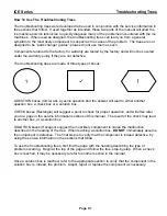
Страница 31: ... answer will lead to either another question box a check box or a solution box CHECK boxes Rectangle will suggest a point to check for proper operation and will often refer you to a page in the service information sections of this manual The result of the check may lead to another box or a solution box SOLUTION boxes Hexagon suggest the most likely component to cause the malfunction described in t...

Страница 32: ...Suction Pressure C8 Cubes Are Hollow C9 Uneven Bridge Thickness C10 Ice Bridge Thickness Varies Cycle To Cycle C11 Machine Produces Cloudy Ice C12 Poor Water Distribution Over Evaporator C13 Machine Does Not Enter Harvest C14 Machine Enters Harvest Then Returns To Freeze Prematurely C15 Length Of Harvest Excessive C16 Ice Does Not Release From Evaporator C17 Hot Evaporator Low Suction Pressure Rem...

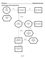
Страница 33: ...ol for proper adjustment see page F9 Is this a Remote unit Is the Liquid line Solenoid energized and open OK OK GOOD TRIPPED OPEN BAD NO NOT OK OK Adjust as required or replace if defective Replace or identify reason for being open Reset and identify reason for high head pressure Correct field wiring deficiency Set selector Switch to the ICE position Selector Switch could be defective see page F1 ...

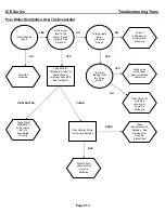
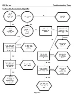
Страница 34: ...mpressor running NO GOOD OK Check Selector Switch Replace if defective Check the suction pressure is it low or high NO OK HIGH LOW OK OK Does the unit have a remote condenser Check High Pressure reset if necessary Continue if the machine has a remote condenser Check refrigerant charge OK Compressor or Start Components could be defective see page F2 Pumpdown Control possibly bad Liquid Line Solenoi...

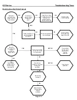
Страница 35: ...ssure is also high make sure Condenser is clean and machine has good air flow Is water leaking out of the Purge Drain or Water Trough NO YES OK LOW SUCTION OK Recover and weigh in refrigerant charge Check Hot Gas Valve for leakage during freeze see page E5 Check for inefficient Compressor OK Low side restriction or defective TXV Repair water leakage defect ...

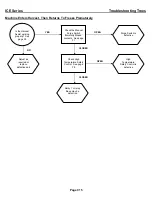
Страница 36: ...r excessive head pressure OK Check Water Regulating Valve See page E2 Check refrigeration system Section E AIR YES TOO HIGH Clean Condenser and Condenser Fan Blade Correct any installation defects Is this unit air cooled or water cooled Is the Air Condenser clean See Condenser service information page E2 Adjust or replace Water Regulating Valve NO WATER NOT OK OK ...

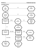
Страница 37: ...ration see page E4 YES YES Go to Troubleshooting Tree on page C12 Is the machine a remote unit Replace drier evacuate and recharge system NO NOT OK OK Is the water flow over the Evaporator correct Low charge locate and repair leak evacuate and recharge system See Troubleshooting Tree page C18 TXV possibly defective see page E3 and page E4 Correct restricted tubing OK OK WET SYSTEM DRY SYSTEM NOT O...

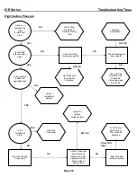
Страница 38: ... Valve YES YES Replace Compressor Go to Slow Production Troubleshooting Tree Is the machine installed to specifications Clean the Condenser NO NOT OK YES Is the head pressure also high TXV could be defective see Expansion Valve see page E3 and E4 Hot Gas Valve is possibility defective Repair or replace defective part TVX Thermal bulb loose or TXV could be defective OK OK NOT OK Check Compressor se...

Страница 39: ...page C13 NO YES YES Purge Valve has an obstruction or could be defective Is water leaking from the Purge Drain NO NOT OK Is there good water flow over the Evaporator OK Check Timer for proper setting see page F4 NO Timer Initiate Control out of adjustment of defective Timer Module requires adjustment or could be defective Water temperature too high correct water temperature ...

Страница 40: ...Dirty or defective Purge Valve Is water running into the bin NO OK Are the Evaporator s flooded See page E4 and E5 Serpentine coil on back of evaporator could be separated see page E4 Check the suction pressure is it high or low See pageE1 LOW Make sure the system is charged properly recover the charge and weigh in the correct amount NO Hot Gas Valve could be leaking see page E5 OK Refer to page E...

Страница 41: ...leaks NO YES OK Correct installation deficiency Replace Timer Initiate OK Clean Purge Valve or replace if defective OK Check Hot Gas valve for proper operation NOT OK Check Timer Initiate Control for proper operation Replace Hot Gas Valve OK Check Solid State Timer for proper operation NOT OK Adjust Timer or replace if defective NOT OK TXV s could be defective see page E3 and E4 ...

Страница 42: ...ter running evenly across the evaporator NO YES See Poor Water Running Over Evaporator Troubleshooting Tree page C13 NO YES Doe machine meet installation guidelines See Section A Cloudiness is a result of properties in the incoming supply water Correct installation deficiency ...

Страница 43: ...er pressure correct NO BAD Is the water level in the Water Trough correct See Section D Purge valve stuck open clean or replace if defective Float Valve not adjusted properly or could be defective YES Check Water Pump for proper operation Water Pump obstructed or may be defective Clean Water Distribution Tube insure that it is assembled correctly NO OBSTRUCTED CLEAR GOOD Clean Evaporator and Spill...

Страница 44: ...the freeze pattern on the Evaporator even TXV s may be stuck open see page E3 and E4 Timer Initiate Control out of adjustment or may be defective YES Check for signs of a weak Compressor see page E1 High Temperature Safety Control may be open see page F8 Check Timer Number 2 NO NOT OK Make sure system is not overcharged Check Timer Initiate Control for correct cut in pressure Check Timer Number 1 ...

Страница 45: ...working properly See page F6 Check the Manual Purge Switch Normally Closed contacts See page F1 Purge Switch is defective OPEN Adjust as required or replace defective part Check High Temperature Safety Control See page F8 OPEN CLOSED CLOSED Relay 1 or relay Base may be defective NO High Temperature Safety Control is defective ...

Страница 46: ... proper charge Is the ice formation even on the Evaporator Adjust or replace defective part Hot Gas Valve may be defective Remote Check Mixing Valve operation page E6 Water Cooled check Water Valve for proper adjustment NOT OK Does the machine have a remote condenser Check suction pressure during harvest See page E5 Clean Evaporator per instructions in Section B OK NO YES YES NO OK OK TOO LOW STIL...

Страница 47: ...Assist for proper operation see page F6 NO Selector Switch may be defective WASH contacts closed in ICE mode Relay or Relay Base defective NO GOOD NOT OK Check Purge valve and Tubing for obstructions and proper operation see page D2 Check Relay 1 and Relay Base for proper operation see page F5 Check suction pressure during harvest see page E5 Check discharge pressure during freeze see page E2 Repa...

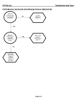
Страница 48: ...ge Pressure Remote Only YES Correct installation deficiency Does the machine have the proper refrigeration charge NO NO YES Does the machine meet the installation guidelines Repair leak evacuate and weigh in refrigerant charge per nameplate Mixing Valve may be defective see page E6 ...

Страница 49: ... trough refills Float Valve The water level can be adjusted by carefully bending the arm of the float The water level should be inch 13mm above the top of the water pump impeller housing during the freeze cycle If the float valve does not allow water into the trough or water flow is slow the float valve may be restricted Remove and disassemble the float valve and clean the orifice If the water flo...

Страница 50: ...ube can be checked for proper assembly by checking the bump on the flanges at the tube ends the bump should be at the top Water Distribution Disassembly Remove 2 screws holding the distribution tube to the evaporator spillway Remove the clamp holding the water tube to the distribution tube Twist the end caps of the distribution tube counterclockwise and pull to remove the inner tube halves from th...

Страница 51: ...n dual evaporator units if the curtain is opened or removed during the untimed freeze cycle or during defrost the machine will shut down If the curtain is opened or removed during the timed freeze cycle the unit will continue to operate The splash curtain can be removed by swinging the bottom of the curtain away from the evaporator and lifting the right side of the curtain up and out of the hinge ...

Страница 52: ...must be completely closed during the freeze cycle If water leaks through the purge valve during the freeze cycle the freeze cycle will be extended due to the float allowing warm water into the trough and poor ice formation will result The purge valve may be defective or need cleaning The purge valve can be disassembled for cleaning by 1 Disconnect electrical power form the ice machine 2 Lift and r...

Страница 53: ...er supply off to the ice machine 3 Remove water splash curtains when applicable 4 Remove water trough mounting screws 5 Carefully remove water trough from the ice machine 6 Reverse procedure to reassemble ICE 22 Inch Wide Models Mounting Screws ICE 30 Inch Wide Models ICE 48 Inch Wide Models Mounting Screws Mounting Screws Mounting Screws Mounting Screws Version 3 Water Trough ICE1506 Model ICEU30...

Страница 54: ...denser The refrigerant changes to a liquid when cooled The refrigerant in a liquid state passes through a filter drier The filter drier traps small amounts of moisture and foreign particles from the system The filter drier must be replaced whenever the refrigeration system is opened or if the refrigerant charge has been completely lost Compressor The compressor runs during the entire cycle If the ...

Страница 55: ... system must be completely evacuated To achieve a complete evacuation you will need a service gauge manifold with properly maintained hoses and a vacuum pump capable of pulling a 50 micron vacuum This will require a two stage pump Connect the service gauge manifold to the high and low side service ports and vacuum pump Make sure the valves on the gauge manifold are closed then start the pump Note ...

Страница 56: ...estricted or not opening properly will starve the evaporator resulting in lower than normal suction pressure A low refrigerant charge will also starve the evaporator and cause low suction and discharge pressures If not sure of the amount of charge in the system the refrigerant should be recovered and the correct charge be weighed in before a defective valve can be diagnosed If the evaporator is st...

Страница 57: ... ice formation Most problems with ice formation or harvesting are not related to a defective evaporator use the Troubleshooting Trees in section C for additional help Refrigerant enters the evaporator through the bottom tube and exits through the top tube On models ICE800 1000 1800 and 2100 the refrigerant line at the TXV outlet splits into two feeder tubes This split occurs at the distributor whi...

Страница 58: ... hot gas valve does not completely open during harvest there will not be enough hot gas in the evaporator to defrost the ice If there is not enough hot gas entering the evaporator the suction pressure will be lower than the above stated pressures It is important when making this check that the machine has the proper refrigerant charge normal head pressure and the compressor is functioning properly...

Страница 59: ...d refrigerant coming from the condenser This change allows the valve to partially restrict the flow of refrigerant leaving the condenser and allows discharge gas to by pass the condenser and flow directly into the receiver mixing with the liquid refrigerant from the condenser The amount of discharge gas that bypasses the condenser increases as the ambient temperature decreases This action of the m...

Страница 60: ...n the condenser and receiver while the machine is off It is normal for the machine to pump down once or twice an hour as the pressures equalize When the machine comes back on the bin switch closes or the selector switch placed to the ICE position the liquid line solenoid valve opens and the refrigerant is released from the receiver When the suction pressure rises to 35 psi 2 38 bar the pump down c...

Страница 61: ...system must be completely evacuated To achieve a complete evacuation you will need a service gauge manifold with properly maintained hoses and a vacuum pump capable of pulling a 50 micron vacuum This will require a two stage pump Connect the service gauge manifold to the high and low side service ports and vacuum pump Make sure the valves on the gauge manifold are closed then start the pump Note D...

Страница 62: ...cern with the icemaker to be accurately diagnosed The refrigerant charge must be weighed into the icemaker either by using a charging scale or with a dial a charge The amount of proper refrigerant required for the icemaker is printed on the serial data plate attached to the icemaker and is listed on the following pages Never vary the amounts from those listed Remote models with sixty 60 foot lines...

Страница 63: ...15 60 1 ICE0250 A T2 R 404a 16 60 37 175 400 37 12 22 3 115 60 1 ICE0250 W2 R 404a 13 60 35 250 35 12 19 3 115 60 1 ICE0250 A4 R 404a 25 60 35 200 400 36 13 17 3 115 60 1 ICE0250 A T4 R 404a 25 60 37 200 400 36 13 17 3 115 60 1 ICE0250 W4 R 404a 13 60 35 250 35 13 16 3 115 60 1 ICE0320 A1 R 404a 18 60 36 175 400 36 14 25 3 115 60 1 ICE0320 W1 R 404a 15 60 36 250 36 12 17 3 115 60 1 ICE0320 A2 R 40...

Страница 64: ...208 230 60 1 ICE0606 A2 R 404a 24 60 35 175 400 35 11 19 5 5 208 230 60 1 ICE0606 A T2 R 404a 24 60 35 175 400 35 11 19 5 5 208 230 60 1 ICE0606 W2 R 404a 18 60 35 250 35 12 17 5 5 208 230 60 1 ICE0606 R2 R 404a 160 60 33 240 400 33 11 18 5 5 208 230 60 1 ICE0606 R3 R 404a 132 60 33 240 400 33 11 18 5 5 208 230 60 1 ICE0606 A3 R 404a 24 60 46 200 400 35 11 15 5 5 208 230 60 1 ICE0606 A T3 R 404a 2...

Страница 65: ... ICE1806 W2 R 404a 35 60 34 250 34 11 17 14 208 230 60 1 ICE1806 R2 R 404a 400 60 37 240 400 37 10 17 14 208 230 60 1 ICE1806 W3 R 404a 37 60 53 250 38 11 13 14 208 230 60 1 ICE1806 R3 R 404a 272 72 61 240 400 38 12 15 14 208 230 60 1 ICE1807 W1 R 404a 42 60 35 250 35 10 16 14 208 230 60 3 ICE1807 R1 R 404a 400 60 35 192 400 35 10 17 14 208 230 60 3 ICE1807 W2 R 404a 35 60 35 250 35 10 16 14 208 2...

Страница 66: ...05 W2 R 404a 14 60 35 250 35 14 21 5 5 220 240 50 1 ICE0605 R2 R 404a 160 60 35 240 400 35 14 22 5 5 220 240 50 1 ICE0605 R3 R 404a 132 60 35 240 400 35 14 22 5 5 220 240 50 1 ICE0605 A3 R 404a 22 50 46 200 400 35 13 18 5 5 220 240 50 1 ICE0605 W3 R 404a 14 47 45 250 32 14 16 5 5 220 240 50 1 ICE0605 R4 R 404a 132 45 43 240 400 35 15 18 5 5 220 240 50 1 ICE0805 A1 R 404a 41 60 35 175 400 35 11 20 ...

Страница 67: ...17 90 70 250 250 80 41 108 130 169 207 66 34 29 19 1 01 30 20 110 100 288 254 95 42 112 137 178 217 82 37 39 52 1 01 40 53 ICEU220A Ambients Refrigeration Pressures PSIG Compressor Temps F Cycle Times F Discharge Suction Discharge Suction Minutes Seconds Air Water Start End Start Freeze End Freeze Start Harv End Harv Start End Start End Freeze Harvest Complete 50 40 191 162 61 31 82 85 110 145 41 ...

Страница 68: ... 03 70 50 257 196 65 28 100 108 118 159 56 35 10 46 0 59 11 45 90 70 296 241 93 31 146 146 138 184 76 54 15 09 0 41 15 50 110 100 381 299 107 33 150 167 166 209 89 57 28 31 0 44 29 15 ICE0250W3 Ambients Refrigeration Pressures PSIG Compressor Temps F Cycle Times F Discharge Suction Discharge Suction Minutes Seconds Air Water Start End Start Freeze End Freeze Start Harv End Harv Start End Start End...

Страница 69: ...5 114 181 70 56 20 20 0 48 21 08 110 100 383 302 110 41 140 170 126 206 90 62 44 06 0 34 44 40 ICE0400W3 Ambients Refrigeration Pressures PSIG Compressor Temps F Cycle Times F Discharge Suction Discharge Suction Minutes Seconds Air Water Start End Start Freeze End Freeze Start Harv End Harv Start End Start End Freeze Harvest Complete 50 40 250 250 63 38 91 98 98 157 45 30 10 47 1 10 11 57 70 50 25...

Страница 70: ...53 90 70 271 245 56 35 66 68 169 193 56 26 15 03 0 51 15 54 110 100 390 340 56 33 66 68 182 233 60 46 29 59 0 56 30 55 ICE0520A3 Ambients Refrigeration Pressures PSIG Compressor Temps F Cycle Times F Discharge Suction Discharge Suction Minutes Seconds Air Water Start End Start Freeze End Freeze Start Harv End Harv Start End Start End Freeze Harvest Complete 50 40 230 248 55 39 80 87 95 149 42 34 9...

Страница 71: ... 10 38 90 70 250 250 54 28 78 85 110 169 53 28 11 33 1 28 13 01 110 100 360 301 74 30 117 135 133 206 81 40 23 43 0 50 24 33 ICE0606R4 Ambients Refrigeration Pressures PSIG Compressor Temps F Cycle Times F Discharge Suction Discharge Suction Minutes Seconds Air Water Start End Start Freeze End Freeze Start Harv End Harv Start End Start End Freeze Harvest Complete 20 40 238 238 46 33 93 86 107 159 ...

Страница 72: ...10 31 90 70 294 272 72 35 118 125 111 177 63 46 11 12 0 56 12 08 110 100 401 326 90 33 136 160 120 216 79 57 22 34 0 50 23 24 ICE1006A Ambients Refrigeration Pressures PSIG Compressor Temps F Cycle Times F Discharge Suction Discharge Suction Minutes Seconds Air Water Start End Start Freeze End Freeze Start Harv End Harv Start End Start End Freeze Harvest Complete 50 40 186 176 50 33 70 68 100 132 ...

Страница 73: ... Minutes Seconds Air Water Start End Start Freeze End Freeze Start Harv End Harv Start End Start End Freeze Harvest Complete 20 40 240 240 61 33 94 101 104 159 53 38 6 44 0 55 7 39 70 50 270 266 72 34 107 112 115 173 58 42 8 36 0 55 9 31 90 70 287 272 77 33 111 117 118 182 60 43 10 21 1 01 11 22 120 100 419 323 93 28 135 150 128 221 77 43 24 34 0 55 25 29 ...

Страница 74: ...n the timer initiate control opens Compressor and Start Components The compressor should run during the entire cycle If the machine is in the ICE position but the compressor is not running check the compressor contactor to see if it is engaged If the contactor is not engaged the problem is not with the compressor or the compressor start components If the contactor is engaged and there is correct v...

Страница 75: ...art capacitor is an electrical storage device used to provide starting torque to the compressor If a start capacitor is defective the compressor will not start properly The run capacitor is an electrical storage device used to improve the running characteristics and efficiency of the compressor Before checking a capacitor it should be discharged by shorting across the terminals If a run or start c...

Страница 76: ...FF Attach one lead of a voltmeter to terminal 1 and the other lead to terminal 2 of the timer initiate control Reconnect incoming power and turn the machine to the ICE position Connect a low pressure gauge to the machine The volt meter should read line voltage until the timer initiate control closes at which point the voltmeter should read zero volts Note the suction pressure at this point Adjust ...

Страница 77: ...n the ICEU undercounter series ICE0250 and ICE0305 and 1 8 3 mm on ICE0400 and larger units If the bridge is too thick remove enough time from the timer to achieve proper thickness If the bridge is too thin add enough time to the timer to achieve proper thickness Bridge Thickness Check the freeze timer for proper operation as follows Make sure that the high temperature safety control is not open s...

Страница 78: ...nes Once the freeze timer has counter out power is sent to A harvest motor 1 and relay coil 1 through the normally closed contacts of cam switch 1 B to harvest motor 2 and relay coil 2 through the normally closed contacts of cam switch 2 The contacts of relay 1B and 2B closing energizes the 4 second hot gas delay timer Right Hand Timer This 4 second delay will allow the harvest motors to rotate an...

Страница 79: ... defective motor to bump backwards immediately when entering harvest This will activate the cam switch and cause the machine to return to the freeze cycle immediately after entering harvest If the machine is in harvest only for a split second the harvest motor may be defective Verify the motor is defective by watching the clutch closely when the machine enters harvest Clutch Assembly The clutch as...

Страница 80: ...art of the cam During freeze power is supplied to the water pump and relay 2 through the normally closed contacts of the cam switch When the machine enters harvest power is supplied to the water pump and purge valve through the normally closed contacts of the cam switch and through the normally open contacts of relay 1 closed during harvest The water pump purge valve and relay 1 remain energized u...

Страница 81: ...trol specifications have been changed to open at 120ْF and close at 100ْF Note 2 On models where the high temperature safety control is mounted on the hot gas valve outlet tube the specifications are open at 180ºF and close at 120 ºF Additionally the high temperature safety control is wired in series with the contactor If the high temperature safety control opens for any reason the compressor will...

Страница 82: ... recheck and make a minor adjustment if needed If a minor adjustment is required turn the adjustment screw clockwise colder or counterclockwise warmer Adjustments are not covered under warranty Pump Down System Remote Only If a remote machine is shut down by the selector switch or bin control the liquid line solenoid valve is de energized allowing the valve to close This blocks the flow of refrige...

Страница 83: ...g hot gas the circuit is latched through the Purge Switch contacts C and NC 9 Relay Number 3A contacts C and NO close to send power to the Selector Switch and Hot Gas Valves when the curtain is open 10 Once Cam Switch 2 contacts C and NO close High Side of the Cam it will remain energized from the Selector Switch until contacts C and NC close Rotates 360 degrees 11 Once Cam Switch 1 contacts C and...

Страница 84: ...1 8 When the Low Pressure Control opens during hot gas defrost the circuit is latched through the Purge Switch contacts C and NC 9 Relay Number 3A contacts C and NO close to send power to the Selector Switch and Hot Gas Valves when the curtain is open 10 Once Cam Switch 2 contacts C and NO close High side of the Cam it will remain energized from the Selector Switch until contacts C and NC close Ro...

Страница 85: ...ay Number 4 Coil 8 Relay Number 1B contacts C and NO close to energize Harvest Motor 1 and Hot Gas Valve 1 9 When the Low Pressure Control opens during hot gas the circuit is latched through the Purge Switch contacts C and NC 10 Once Cam Switch 2 contacts C and NO close High side of the Cam it will remain energized from the Selector Switch until contacts C and NC close Rotates 360 degrees 11 Once ...

Страница 86: ...ICE Series Wiring Diagram Page G1 ICEU150 200 205 206 Air and Water Wiring Diagram ...

Страница 87: ...ICE Series Wiring Diagram Page G2 ICEU150 200 205 206 Air and Water Wiring Schematic ...

Страница 88: ...ICE Series Wiring Diagram Page G3 ICEU150 220 225 226 Air and Water Wiring Diagram ...

Страница 89: ...ICE Series Wiring Diagram Page G4 ICEU150 220 225 226 Air and Water Wiring Schematic ...

Страница 90: ...ICE Series Wiring Diagram Page G5 ICE0250 Air and Water Wiring Diagram ...

Страница 91: ...ICE Series Wiring Diagram Page G6 ICE0250 Air and Water Wiring Schematic ...

Страница 92: ...ICE Series Wiring Diagram Page G7 ICE0400 Air and Water Wiring Diagram ...

Страница 93: ...ICE Series Wiring Diagram Page G8 ICE0400 Air and Water Wiring Schematic ...

Страница 94: ...ICE Series Wiring Diagram Page G9 ICE0405 0406 Air and Water Wiring Diagram ...

Страница 95: ...ICE Series Wiring Diagram Page G10 ICE0405 0406 Air and Water Wiring Schematic ...

Страница 96: ...ICE Series Wiring Diagram Page G11 ICE0500 Air and Water Wiring Diagram ...

Страница 97: ...ICE Series Wiring Diagram Page G12 ICE0500 Air and Water Wiring Schematic ...

Страница 98: ...ICE Series Wiring Diagram Page G13 ICE0500 Remote Wiring Diagram ...

Страница 99: ...ICE Series Wiring Diagram Page G14 ICE0500 Remote Wiring Schematic ...

Страница 100: ...ICE Series Wiring Diagram Page G15 ICE0605 0606 0805 0806 1005 1006 Air and Water Wiring Diagram ...

Страница 101: ...ICE Series Wiring Diagram Page G16 ICE0605 0606 0805 0806 1005 1006 Air and Water Wiring Schematic ...

Страница 102: ...ICE Series Wiring Diagram Page G17 ICE0605 0606 0805 0806 1005 1006 Remote Wiring Diagram ...

Страница 103: ...ICE Series Wiring Diagram Page G18 ICE0605 0606 0805 0806 1005 1006 Remote Wiring Schematic ...

Страница 104: ...ICE Series Wiring Diagram Page G19 ICE1007 Air and Water Wiring Diagram ...

Страница 105: ...ICE Series Wiring Diagram Page G20 ICE1007 Air and Water Wiring Schematic ...

Страница 106: ...ICE Series Wiring Diagram Page G21 ICE1007 Remote Wiring Diagram ...

Страница 107: ...ICE Series Wiring Diagram Page G22 ICE1007 Remote Wiring Schematic ...

Страница 108: ...ICE Series Wiring Diagram Page G23 ICE1405 1406 1806 2005 2106 Air and Water Wiring Diagram ...

Страница 109: ...ICE Series Wiring Diagram Page G24 ICE1405 1406 1806 2005 2106 Air and Water Wiring Schematic ...

Страница 110: ...ICE Series Wiring Diagram Page G25 ICE1405 1406 1806 2005 2106 Remote Wiring Diagram ...

Страница 111: ...ICE Series Wiring Diagram Page G26 ICE1405 1406 1806 2005 2106 Remote Wiring Schematic ...

Страница 112: ...ICE Series Wiring Diagram Page G27 ICE1407 1807 2107 Air and Water Wiring Diagram ...

Страница 113: ...ICE Series Wiring Diagram Page G28 ICE1407 1807 2107 Air and Water Wiring Schematic ...

Страница 114: ...ICE Series Wiring Diagram Page G29 ICE1407 1807 2107 Remote Wiring Diagram ...

Страница 115: ...ICE Series Wiring Diagram Page G30 ICE1407 1807 2107 Remote Wiring Schematic ...

Страница 116: ...ICE Series Wiring Diagram Page G31 ICE1606 Remote Wiring Diagram ...

Страница 117: ...ICE Series Wiring Diagram Page G32 ICE1606 Remote Wiring Schematic ...

Страница 118: ...ICE Series Wiring Diagram Page G33 ICE0320 Air and Water Wiring Diagram ...

Страница 119: ...ICE Series Wiring Diagram Page G34 ICE0320 Air and Water Wiring Schematic ...

Страница 120: ...ICE Series Wiring Diagram Page G35 ICE0520 Air and Water Wiring Diagram ...

Страница 121: ...ICE Series Wiring Diagram Page G36 ICE0520 Air and Water Wiring Schematic ...

Страница 122: ...ICE Series Wiring Diagram Page G37 ICE0325 0525 Air and Water Wiring Diagram ...

Страница 123: ...ICE Series Wiring Diagram Page G38 ICE0325 0525 Air and Water Wiring Schematic ...

Страница 124: ...ICE Series Wiring Diagram Page G39 ICE0305 Air and Water Wiring Diagram ...

Страница 125: ...ICE Series Wiring Diagram Page G40 ICE0305 Air and Water Wiring Schematic ...

Страница 126: ...ICE Series Wiring Diagram Page G41 ICE1506 Remote ...

Страница 127: ...ICE Series Wiring Diagram Page G42 ICE1506 Remote ...

Страница 128: ...ICE Series Wiring Diagram Page G43 ICEU300 Air and Water ...

Страница 129: ...ICE Series Wiring Diagram ICEU300 Air and Water Page G44 ...

Страница 130: ...ICE Series Wiring Diagram Page G45 ICEU305 Air and Water ...

Страница 131: ...ICE Series Wiring Diagram Page G46 ICEU305 Air and Water ...

Страница 132: ...ICE Series Wiring Diagram Page G47 ICE0500 Remote Wiring Diagram R3 ...

Страница 133: ...ICE Series Wiring Diagram Page G48 ICE0500 Remote Wiring Schematic R3 ...

Страница 134: ...ICE Series Wiring Diagram ICE0605 0606 0806 1006 Remote Wiring Diagram R3 Page G49 ...

Страница 135: ...ICE Series Wiring Diagram Page G50 ICE0605 0606 0806 1006 Remote Wiring Schematic R3 ...

Страница 136: ...ICE Series Wiring Diagram Page G51 ICE1007 Remote Wiring Diagram R3 ...

Страница 137: ...ICE Series Wiring Diagram Page G52 ICE1007 Remote Wiring Schematic R3 ...

Страница 138: ...ICE Series Wiring Diagram Page G53 ICE0250 Air4 and Water4 ICE0400 Air3 and Water3 Wiring Diagram ...

Страница 139: ...ICE Series Wiring Diagram Page G54 ICE0250 Air4 and Water4 ICE0400 Air3 and Water3 Wiring Schematic ...

Страница 140: ...ICE Series Wiring Diagram Page G55 ICE0320 Air3 and Water3 ICE0520 Air3 and Water3 Wiring Diagram ...

Страница 141: ...ICE Series Wiring Diagram ICE0320 Air4 and Water4 ICE0520 Air3 and Water3 Wiring Schematic Page G56 ...

Страница 142: ...ICE Series Wiring Diagram Page G57 ICE0406 405 Air3 and Water3 ICE0305 Air3 and Water3 Wiring Diagram ...

Страница 143: ...ICE Series Wiring Diagram Page G58 ICE0406 405 Air3 and Water3 ICE0305 Air3 and Water3 Wiring Schematic ...

Страница 144: ...ICE Series Wiring Diagram Page G59 ICE0325 Air3 and Water3 ICE0525 Air3 and Water3 Wiring Diagram ...

Страница 145: ...ICE Series Wiring Diagram ICE0325 Air3 and Water3 ICE0525 Air3 and Water3 Wiring Schematic Page G60 ...

Страница 146: ...ICE Series Wiring Diagram ICE0500 Air3 and Water3 Wiring Diagram Page G61 ...

Страница 147: ...ICE Series Wiring Diagram Page G62 ICE0500 Air3 and Water3 Wiring Schematic ...

Страница 148: ...ICE Series Wiring Diagram Page G63 ICE0500 Remote4 Wiring Diagram ...

Страница 149: ...ICE Series Wiring Diagram Page G64 ICE0500 Remote4 Wiring Schematic ...

Страница 150: ...ICE Series Wiring Diagram ICE0606 Air3 and Water3 ICE0605 Air3 and Water3 Wiring Diagram Page G65 ...

Страница 151: ...ICE Series Wiring Diagram Page G66 ICE0606 Air3 and Water3 ICE0605 Air3 and Water3 ...

Страница 152: ...ICE Series Wiring Diagram ICE0606 Remote4 and ICE0605 Remote4 Wiring Diagram Page G67 ...

Страница 153: ...ICE Series Wiring Diagram Page G68 ICE0606 Remote4 and ICE0605 Remote4 Wiring Schematic ...

Страница 154: ...ICE Series Wiring Diagram Page G68 ICE0606 Remote4 and ICE0605 Remote4 Wiring Schematic ...

Страница 155: ...ICE Series Wiring Diagram ICE1405 6A3 W3 ICE1806W3 and ICE2106W3 Wiring Diagram Page G69 ...

Страница 156: ...ICE Series Wiring Diagram Page G70 ICE1405 6A3 W3 ICE1806W3 and ICE2106W3 Wiring Schematic ...

Страница 157: ...ICE Series Wiring Diagram ICE1407A3 W3 ICE1807W3 and ICE2107W3 Wiring Diagram Page G71 ...

Страница 158: ...ICE Series Wiring Diagram Page G72 ICE1407A3 W3 ICE1807W3 and ICE2107W3 Wiring Schematic ...

Страница 159: ...ICE Series Wiring Diagram Page G73 ICE1405 6R3 ICE1806R3 and ICE2106R3 Wiring Diagram ...

Страница 160: ...ICE Series Wiring Diagram Page G74 ICE1405 6R3 ICE1806R3 and ICE2106R3 Wiring Schematic ...

Страница 161: ...ICE Series Wiring Diagram Page G75 ICE1407R3 ICE1807R3 and ICE2107R3 Wiring Diagram ...

Страница 162: ...ICE Series Wiring Diagram Page G76 ICE1407R3 ICE1807R3 and ICE2107R3 Wiring Schematic ...

Страница 163: ...ICE Series Wiring Diagram Page G77 ICE1506R3 Wiring Diagram ...

Страница 164: ...ICE Series Wiring Diagram Page G78 ICE1506R3 Wiring Schematic ...

Отзывы: