Digital Bidirectional Talk System
Installation Guide
V1.2.0
Страница 1: ...Digital Bidirectional Talk System Installation Guide V1 2 0...
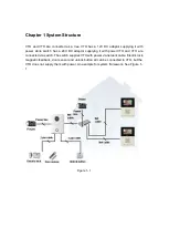
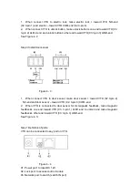
Страница 2: ...as a 24V DC adaptor supplying it with power VTO and VTH are connected via switch The switch supplies VTH with power via network cable Electric lock magnetic feedback door sensor and unlock button all...
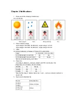
Страница 3: ...etween VTO and VTH select cable Cable 0 LN 50m 50 LN 100m UTP Cat5e Cat6 10 ohm 100m Ok Ok UTP Cat5e Cat6 18 8 ohm 100m Ok Not ok We do not recommend LN over 100m 4 Power line According to distance LC...
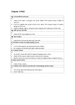
Страница 4: ...volume and call volume with VTH Q VTH has no video or video quality is poor A 1 In VTO web interface switch video format to WVGA 2 Do not place VTO under poor light or direct sunlight Q I cannot unlo...
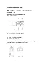
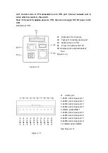
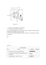
Страница 5: ...etwork port Figure 4 1 01 Network port to external switch IN port 02 3 pin 1 to lock control end 1 03 3 pin 2 to lock control end 2 04 Power port to input 12V DC power 05 Test port to test device port...
Страница 6: ...1 When connect VTO to door sensor make door sensor toward VTO 02 3 pin 2 NC end and door sensor toward VTO 02 3 pin 3 COM end 2 When VTO is connected to door sensor for its magnetic feedback make mag...
Страница 7: ...Step 2 Install electric lock and unlock button See Figure 4 6 Figure 4 6 When Villa VTO connects to electric lock electric lock s positive end connects to NO end 10 pin port 2 of villa VTO and electri...
Страница 8: ...to door feedback inside door lock one end of door feedback connects to ALM2 end 10 pin port 6 of villa VTO and the other end of door feedback connects to GND end 10 pin port 4 of villa VTO 4 1 2 Fix...
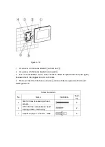
Страница 9: ...ot found Figure 4 9 1 Use screw b to fix bracket onto 86 box embedded 120 box embedded inside 2 Use screw c to fix bracket on 3 Install VTO on VTH bracket and fix with screw a See Figure 4 9 Error Ref...
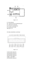
Страница 10: ...02 Test port to testing device port 03 Network port to VTH 04 Power to external DC 12V 05 Handset port external handset See Figure 4 10 Figure 4 10 01 Alarm port 1 ALM1 alarm input port 1 2 ALM2 alarm...
Страница 11: ...rt 8 ch alarms 04 Power to external DC 12V 05 Network port to VTH See Figure 4 12 03 Alarm port definition is as follows Figure 4 13 1 ALM1 alarm input port 1 2 ALM2 alarm input port 2 3 ALM3 alarm in...
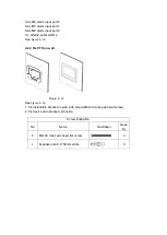
Страница 12: ...2 See Figure 4 13 4 2 2 Fix VTH on wall Figure 4 14 See Figure 4 14 1 Fix installation bracket on wall with screw M4x30 cross pan head screw 2 Fix device onto bracket via buckle Screw Illustration No...
Страница 13: ...ll and push lightly downward until it is plugged into slot on bracket 4 Remove Insert small screwdriver into hole on device and push device upward until removed See Figure 4 15 Screw Illustration No N...
Страница 14: ...against wall and push lightly downward until it is plugged into slot on bracket 4 Remove Insert tool into hole on device and push device upward until removed See Figure 4 16 Screw Illustration No Nam...
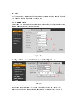
Страница 15: ...input VTO IP and input account password admin admin Then Go to Local Config and set Video Format to WVGA See Figure 4 17 Figure 4 17 Go to System Time click on Sync PC and click on OK See Figure 4 18...
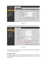
Страница 16: ...r group call VTH is classified into main VTH extension There can have a maximum of 1 main VTH and 5 extensions 4 3 2 Main VTH Setup Enter Project Settings of main VTH password 002236 Product Info set...
Страница 17: ...as in Main VTH Setup Enter Project Settings of extension Product Info click on Master button to switch to extension For example set room no to 102 1 Input master IP in corresponding field When you are...
Страница 18: ...Figure 4 23...
Страница 19: ...dly use period EFUP period the toxic or hazardous substance or elements contained in products will not leak or mutate so that the use of these substances or elements will not result in any severe envi...