background image

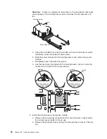
Attention:

Failure to complete the instructions in the prescribed order might

cause damage to the microprocessor pins and cause the microprocessor to
fail.

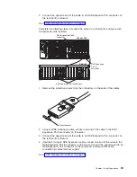
Power module

Microprocessor

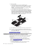
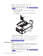
a. Using the T-handled Torx wrench provided with the microprocessor option,

completely loosen the power-module screws.

b. Slide the power module from the microprocessor and remove the power

module.

c. Completely loosen the heat-sink screws.

d. Use the hex wrench provided with the microprocessor option to open the

socket lock and remove the microprocessor.

Unlocked

Locked

Locking
flag

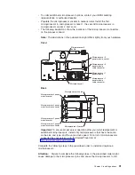
9. Install the microprocessor and power module:

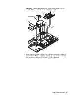
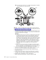
a. Remove the microprocessor baffle from the microprocessor socket. Keep

the microprocessor baffle for future use.

b. Remove the protective tape covering the microprocessor socket, if there is

any.

34

xSeries 455: Option Installation Guide

Содержание xSeries 455

Страница 1: ...xSeries 455 Option Installation Guide ERserver...

Страница 2: ......

Страница 3: ...xSeries 455 Option Installation Guide SC88 P919 80 ERserver...

Страница 4: ...general information in Notices on page 63 First Edition November 2003 Copyright International Business Machines Corporation 2003 All rights reserved US Government Users Restricted Rights Use duplicat...

Страница 5: ...power supply 18 Installing an adapter 19 Cabling a ServeRAID adapter 22 Installing a hot swap hard disk drive 24 Installing a CD ROM or DVD ROM drive 25 Installing memory 26 Removing and replacing DIM...

Страница 6: ...ion FCC statement 66 Industry Canada Class A emission compliance statement 66 Australia and New Zealand Class A statement 66 United Kingdom telecommunications safety requirement 66 European Union EMC...

Страница 7: ...schriften Ennen kuin asennat t m n tuotteen lue turvaohjeet kohdasta Safety Information Avant d installer ce produit lisez les consignes de s curit Vor der Installation dieses Produkts die Sicherheits...

Страница 8: ...ever turn on any equipment when there is evidence of fire water or structural damage v Disconnect the attached power cords telecommunications systems networks and modems before you open the device cov...

Страница 9: ...es or regulations Statement 3 CAUTION When laser products such as CD ROMs DVD drives fiber optic devices or transmitters are installed note the following v Do not remove the covers Removing the covers...

Страница 10: ...ton on the device and the power switch on the power supply do not turn off the electrical current supplied to the device The device also might have more than one power cord To remove all electrical cu...

Страница 11: ...ices 82 kg 180 lb WARNING Handling the cord on this product or cords associated with accessories sold with this product will expose you to lead a chemical known to the State of California to cause can...

Страница 12: ...x xSeries 455 Option Installation Guide...

Страница 13: ...his printed publication contains instructions for installing your server in a rack v Hardware Maintenance Manual and Troubleshooting Guide This publication is in PDF on the IBM xSeries Documentation C...

Страница 14: ...you avoid inconvenient or problem situations v Attention These notices indicate potential damage to programs devices or data An attention notice is placed just before the instruction or situation in w...

Страница 15: ...remove these components while the server is running provided that the server is configured to support hot swap and hot plug features The blue color on components and labels indicates touch points whe...

Страница 16: ...DIMM access doors Fan 4 Fan 3 N O T E F O R P R O P E R A IR F LO W R E P LA C E FA N W IT H IN 2 M IN U T E S F R O N T O F B O X N O T E F O R P R O P E R A IR F LO W R E P LA C E FA N W IT H IN 2 M...

Страница 17: ...D Memory board error LED VRM error LED Processor board internal connectors and LEDs The following illustrations show the internal connectors and LEDs on the processor board Microprocessor 1 power modu...

Страница 18: ...rocessor 2 socket Microprocessor 4 socket Microprocessor 4 power module socket Microprocessor 2 power module socket Microprocessor 2 power module cable connector Microprocessor 4 power module cable co...

Страница 19: ...z PCI X slot 2 66 MHz PCI X slot 3 100 MHz PCI X slot 4 100 MHz PCI X slot 5 133 MHz PCI X slot 6 133 MHz Attention LED Power LED Memory board internal connectors and LEDs The following illustration s...

Страница 20: ...g enabled LED I O board internal connectors The following illustration shows the internal connectors on the I O board Power reset connector Media bays connector Fans 1 and 2 connectors Fan 4 connector...

Страница 21: ...d cannot be diagnosed or the ASM processor has failed The error is not represented by a Light Path Diagnostic LED Check the system error log for more information about the error CPU A microprocessor h...

Страница 22: ...ture is not too high See the User s Guide on the IBM xSeries Documentation CD for temperature information If the problem remains call for service NMI A machine check error has occurred Check the error...

Страница 23: ...h diagnostics continued LED Problem Action OVER SPEC The power supplies are using more power than the maximum rating Replace the failed power supply or remove optional devices from the server Chapter...

Страница 24: ...12 xSeries 455 Option Installation Guide...

Страница 25: ...of supported options for your server go to http www ibm com pc us compat Note Some preconfigured servers have a unique list of supported options See the software documentation that comes with those se...

Страница 26: ...onds This drains static electricity from the package and from your body v Remove the device from its package and install it directly into the system unit without setting down the device If it is neces...

Страница 27: ...connected to ac power the server can respond to requests from the service processor such as a remote request to turn on the server To remove all power from the server you must disconnect it from the p...

Страница 28: ...he Hardware Maintenance Manual and Troubleshooting Guide on the IBM xSeries Documentation CD Opening the cover Complete the following steps to open the server cover 1 Read the safety information begin...

Страница 29: ...r C E C 1 L ig h t P a t h D ia g n o s t ic s Complete the following steps to replace the bezel 1 Align the four tabs on the bezel with the slots in the server chassis 2 Press firmly against the fro...

Страница 30: ...t 100 127 V ac 3 During normal operation both power supplies must be installed for proper operation and cooling If you install or remove a power supply observe the following precautions Statement 8 CA...

Страница 31: ...that the power supply is operating correctly 6 Replace the front bezel on the server see Removing and replacing the bezel on page 16 Installing an adapter Attention Before you remove or replace the R...

Страница 32: ...our server supports six hot plug 64 bit adapters in the expansion slots on the PCI X board as shown in the following table Bus Slot Supported adapter speed MHz A 1 66 A 2 66 B 3 100 133 if slot 4 is e...

Страница 33: ...n page 14 1 Read the safety information beginning on page v and Installation guidelines on page 13 2 Disable the PCI X slot through your operating system before you insert or remove a PCI or PCI X ada...

Страница 34: ...ot If you have other options to install or remove do so now Otherwise go to Completing the installation on page 41 Cabling a ServeRAID adapter Some xSeries 455 models come with an optional IBM ServeRA...

Страница 35: ...X slot see Installing an adapter on page 19 Install the ServeRAID adapter in PCI X slot 6 if the adapter will control the internal hard disk drives Connect to SCSI backplane Preinstalled SCSI cable C...

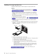
Страница 36: ...me with the drive for more information about installing the drive 4 Remove the filler panel or defective hard disk drive from the hard disk drive bay Attention Only replace a hard disk drive if the am...

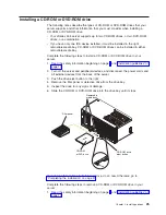
Страница 37: ...isconnect the power cords and all external devices from the back of the server 3 Push the drive eject button to the right 4 Remove the filler panel or defective drive from the drive bay 5 Inspect the...

Страница 38: ...rver supports 512 MB 1 GB and 2 GB DIMMs for a maximum of 56 GB of system memory Your server supports up to twenty eight 2 5 V 184 pin PC2100 ECC DDR SDRAM 133 MHZ DIMMs Go to the ServerProven list at...

Страница 39: ...em with a DIMM is detected light path diagnostics will light the system error LED on the front of the server indicating that there is a problem and guide you to the defective DIMM When this occurs fir...

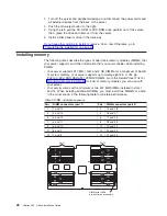
Страница 40: ...covers the DIMM connector into which you will be installing the DIMM 4 Install the new DIMM a Open the retaining clip on each end of the DIMM connector b Touch the static protective package containing...

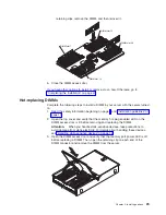
Страница 41: ...d Installation guidelines on page 13 2 Open the top cover and verify that the memory hot plug enabled LED on the DIMM access door is lit before removing and replacing the DIMM Attention When you handl...

Страница 42: ...MM slot 15 DIMM slot 1 DIMM slot 28 DIMM slot 14 5 Close the DIMM access door and verify that the memory port power LED is lit Note The memory hot plug enabled LED flashes to indicate that data is bei...

Страница 43: ...wer module socket Microprocessor 1 Back Microprocessor 2 socket Microprocessor 4 socket Microprocessor 4 power module socket Microprocessor 2 power module socket Microprocessor 2 power module cable co...

Страница 44: ...emory board assembly b Carefully remove the memory board assembly from the server and set it aside N O T E F O R P R O P E R A IR F L O W R E P L A C E FA N W IT H IN 2 M IN U T E S F R O N T O F B O...

Страница 45: ...uring the processor board assembly and pull up on the levers to release the processor board assembly b Slide the assembly toward the right side of the server c Carefully remove the processor board ass...

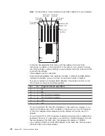
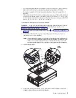
Страница 46: ...ule from the microprocessor and remove the power module c Completely loosen the heat sink screws d Use the hex wrench provided with the microprocessor option to open the socket lock and remove the mic...

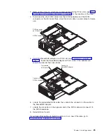
Страница 47: ...cessor to fail Power module Microprocessor Microprocessor baffle c Make sure that the socket lock is in the fully open unlocked position to permit inserting the microprocessor Use the hex wrench that...

Страница 48: ...in the closed position Also note the resistance of the locking mechanism in the closed position When installing the microprocessor do not force the socket lock clockwise beyond the closed position If...

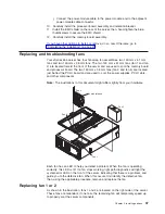
Страница 49: ...to cool the power supplies PCI X slots and other components Note The illustrations in this document might differ slightly from your hardware Fan 1 Fan 2 Fan 3 Fan 4 N O T E F O R P R O P E R A IR F L...

Страница 50: ...B O X Latch release b Lift the fan out of the server 3 Turn the new fan so that the LED on the top of the fan is to the right side of the server 4 Push the replacement fan assembly into the server un...

Страница 51: ...W IT H IN 2 M IN U T E S F R O N T O F B O X Latch release b Grasp the handle and lift the fan out of the server 3 Turn the new fan so that the latch release on the top of the fan is to the right side...

Страница 52: ...ntaining a lithium battery replace it only with the same module type made by the same manufacturer The battery contains lithium and can explode if not properly used handled or disposed of Do not v Thr...

Страница 53: ...e server 9 Start the Configuration Setup Utility program and set configuration parameters v Set the system date and time v Set the power on password v Reconfigure your server Completing the installati...

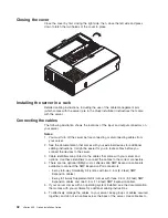
Страница 54: ...at comes with your external devices for additional cabling instructions It might be easier for you to route cables before you connect the devices to the server 3 Cable identifiers are printed on the c...

Страница 55: ...ps to configure and cable a multi node configuration 1 Update the SAL EFI code and the service processor firmware To download the most current level of SAL EFI code and service processor firmware go t...

Страница 56: ...llustration 1 2 3 1 2 3 Node 1 Node 2 3 Connect the SMP Expansion cables to node 1 a Connect one end of an SMP Expansion cable to port 1 on node 1 then route the cable through the node 1 cable managem...

Страница 57: ...connection is needed so that the Remote Supervisor Adapters can communicate and manage scalable partitions 6 Route any remaining cables through the cable management arms 7 Secure the cables in the cab...

Страница 58: ...through the node 1 cable management arm Use a 2 5 m 8 2 feet SMP Expansion cable for this connection b Connect one end of an SMP Expansion cable to port 2 on node 1 then route the cable through the no...

Страница 59: ...de 3 cable management arm b Locate the SMP Expansion cable that is connected to port 2 on node 2 then connect the opposite end of the cable to port 2 of node 3 Next route the cable through the node 3...

Страница 60: ...nnectors on the rear of the server Use these ports to connect the server to a remote I O enclosure and to expand the number of PCI X slots that are available for use by the server For detailed informa...

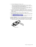
Страница 61: ...the connectors on the ends of the cables Protective cover 2 Using an RXE Expansion cable connect one end of the cable to the RXE Expansion Port A connector on the server 3 Connect the opposite end of...

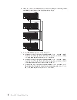
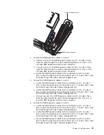
Страница 62: ...the opposite end of the cable to the RXE Expansion Port A connector on the applicable server 5 Using an RXE Expansion cable connect one end of the cable to the RXE Expansion Port B connector on the re...

Страница 63: ...connector on the primary server to the remote I O enclosure 2 You can connect a remote I O enclosure to nodes 1 and 2 or nodes 3 and 4 of a four node configuration You can also connect remote I O enc...

Страница 64: ...Complete the following steps to connect the server RXE Management Port connector to a remote I O enclosure Note Use the following instructions regardless of whether your remote I O enclosure has one...

Страница 65: ...of the cable to the RXE Management Port connector on the other server 4 Connect the opposite end of the cable to the RXE Management A in Port connector on the remote I O enclosure Multi node configur...

Страница 66: ...be connected to a primary power unit inside the rack cabinet such as a properly grounded power distribution unit or uninterruptible power supply Complete the following steps to connect the power cord...

Страница 67: ...nectors on the back of the server Use these connectors to connect the server to a LAN Note A third Ethernet connector is on the Remote Supervisor Adapter This connector is used for specific supervisor...

Страница 68: ...You can use the xSeries 455 Backup and Restore utilities to back up or restore the nonvolatile EFI variables that are stored in NVRAM Creating a backup copy of the nonvolatile EFI variables Complete t...

Страница 69: ...EFI variables 5 Type dir or Is to verify that the backup file was created successfully 6 Type the following EFI command to restore the EFI variables restore filename where filename is the name you as...

Страница 70: ...58 xSeries 455 Option Installation Guide...

Страница 71: ...s and LEDs Ethernet LEDs Gigabit Ethernet connectors RXE Expansion Port A connector Video connector USB 2 connector USB 1 connector RXE Management Port connector SCSI connector Serial connector SMP Ex...

Страница 72: ...emote I O enclosure The following illustration shows an RXE Expansion Port connector 2 1 48 47 RXE Management Port connector Use the RXE Management Port connector to connect your server to a remote I...

Страница 73: ...l Serial Bus USB connector to connect a USB device USB technology transfers data at up to 12 Mb per second Mbps with a maximum of 127 devices and a maximum signal distance of 5 meters 16 ft per segmen...

Страница 74: ...62 xSeries 455 Option Installation Guide...

Страница 75: ...Y OF ANY KIND EITHER EXPRESS OR IMPLIED INCLUDING BUT NOT LIMITED TO THE IMPLIED WARRANTIES OF NON INFRINGEMENT MERCHANTABILITY OR FITNESS FOR A PARTICULAR PURPOSE Some states do not allow disclaimer...

Страница 76: ...or both Microsoft Windows and Windows NT are trademarks of Microsoft Corporation in the United States other countries or both UNIX is a registered trademark of The Open Group in the United States and...

Страница 77: ...ibility gaskets and connectors which may contain lead and copper beryllium alloys that require special handling and disposal at end of life Before this unit is disposed of these materials must be remo...

Страница 78: ...operate the equipment This device complies with Part 15 of the FCC Rules Operation is subject to the following two conditions 1 this device may not cause harmful interference and 2 this device must a...

Страница 79: ...t may cause radio interference in which case the user may be required to take adequate measures Taiwanese Class A warning statement Chinese Class A warning statement Japanese Voluntary Control Council...

Страница 80: ...f Czech Republic Dahomey Djibouti Egypt Equatorial Guinea Eritrea Estonia Ethiopia Finland France French Guyana French Polynesia Germany Greece Guadeloupe Guinea Guinea Bissau Hungary Iceland Indonesi...

Страница 81: ...Philippines Taiwan United States of America Venezuela 24P6858 Korea Democratic People s Republic of Korea Republic of 34G0232 Japan 36L8880 Argentina Paraguay Uruguay 49P2078 India 49P2110 Brazil 6952...

Страница 82: ...70 xSeries 455 Option Installation Guide...

Страница 83: ...2 DIMMs considerations 28 hot swap 26 order of installation 26 E electronic emission Class A notice 66 expansion enclosure 52 expansion slots location 19 type 19 F fan assemblies 37 fans replacing an...

Страница 84: ...ld 14 R reliability system 13 removing memory board assembly 30 microprocessor board assembly 30 replacing fans 1 and 2 37 fans 3 and 4 38 RXE Remote Expansion Enclosure 51 54 RXE Expansion Port conne...

Страница 85: ......

Страница 86: ...Part Number 88P9198 Printed in U S A SC88 P919 80 1P P N 88P9198...

Отзывы: