


v
Follow
the
suggested
actions
in
the
order
in
which
they
are
listed
in
the
Action
column
until
the
problem
is
solved.
v
See
to
determine
which
components
are
customer
replaceable
units
(CRU)
and
which
components
are
field
replaceable
units
(FRU).
v
If
an
action
step
is
preceded
by
“(Trained
service
technician
only)”,
that
step
must
be
performed
only
by
a
trained
service
technician.
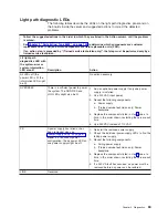
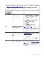
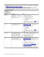
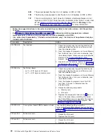
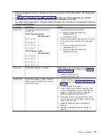
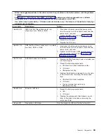
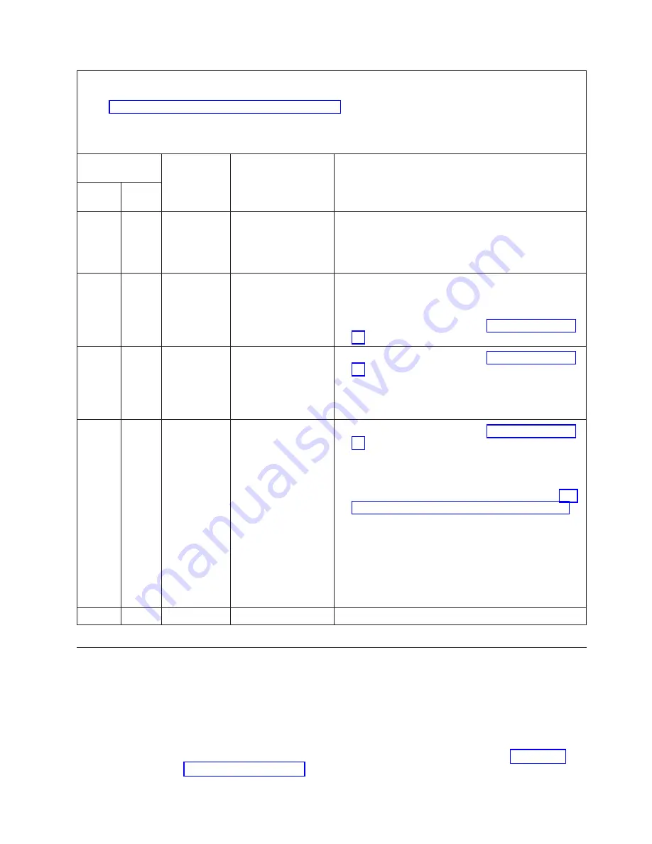
Power-supply
LEDs
Operator
information
panel
power
LED
Description
Action
AC
good
DC
good
Off
Off
Off
No
power
to
the
server,
or
a
problem
with
the
ac
power
source.
1.
Check
the
ac
power
to
the
server.
2.
Make
sure
that
the
power
cord
is
connected
to
a
functioning
power
source.
3.
Remove
one
power
supply
at
a
time.
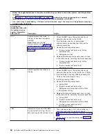
Lit
Off
Off
DC
source
power
problem
1.
Make
sure
that
the
microprocessor
tray
is
connected
to
the
power
backplane.
2.
Remove
one
power
supply
at
a
time.
3.
View
the
system-error
log
(see
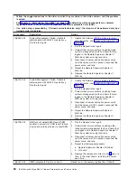
Lit
Lit
Off
Standby
power
problem
1.
View
the
system-error
log
(see
2.
Isolate
by
removing
one
power
supply
at
a
time.
3.
(Trained
service
technician
only)
Replace
the
power
backplane.
Lit
Lit
Flashing
System
power-on
problem
1.
View
the
system-error
log
(see
2.
Press
the
power-control
button
on
the
operator
information
panel.
3.
(Trained
service
technician
only)
Use
the
force-power-on
jumper
as
a
debugging
aid
(see
to
determine
whether
the
information
panel
switch
and
cable
are
faulty.
4.
Remove
the
optional
Remote
Supervisor
Adapter
II
SlimLine,
and
try
to
turn
on
the
server.
5.
Reseat
the
microprocessor
tray.
6.
(Trained
service
technician
only)
Replace
the
microprocessor
tray.
Lit
Lit
Lit
The
power
is
good.
No
action.
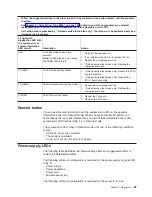
Diagnostic
programs,
messages,
and
error
codes
The
server
diagnostic
programs
are
the
primary
method
of
testing
the
major
components
of
the
server.
As
you
run
the
diagnostic
programs,
text
messages
and
error
codes
are
displayed
on
the
screen
and
are
saved
in
the
test
log.
A
diagnostic
text
message
or
error
code
indicates
that
a
problem
has
been
detected;
to
determine
what
action
you
should
take
as
a
result
of
a
message
or
error
code,
see
the
table
in
Chapter
2.
Diagnostics
69
Содержание xSeries 366
Страница 1: ...IBM xSeries 366 Type 8863 Problem Determination and Service Guide...
Страница 2: ......
Страница 3: ...IBM xSeries 366 Type 8863 Problem Determination and Service Guide...
Страница 8: ...vi IBM xSeries 366 Type 8863 Problem Determination and Service Guide...
Страница 28: ...12 IBM xSeries 366 Type 8863 Problem Determination and Service Guide...
Страница 160: ...144 IBM xSeries 366 Type 8863 Problem Determination and Service Guide...
Страница 170: ...154 IBM xSeries 366 Type 8863 Problem Determination and Service Guide...
Страница 181: ...V video connector 6 VRM LED 64 W Web site 1 weight 3 World Wide Web 1 Index 165...
Страница 182: ...166 IBM xSeries 366 Type 8863 Problem Determination and Service Guide...
Страница 183: ......
Страница 184: ...Part Number 31R1508 Printed in USA 1P P N 31R1508...


