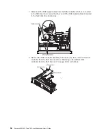
22. Connect the SAS signal cables to the connectors on the SAS controller:
a. Connect the shorter SAS signal cable that comes with the option kit to the
SAS controller connector that is labeled “Ports 7-4”. If you are connecting
cables to a ServeRAID-MR10i SAS/SATA Controller, this connector is
closest to the edge of the controller and has two straight connectors.
Note: If you are connecting the shorter SAS signal cable to a
ServeRAID-BR10i SAS/SATA Controller, the connectors are reversed. You
must connect the shorter SAS signal cable to the connector that is labeled
“Port 4–7”, which is the connector that is not the closest to the edge of the
controller.
PCI
riser-card
assembly
ServeRAID-MR10i
SAS/SATA controller
SAS controller
connectors
Shorter SAS
signal cable
(two straight
connector ends)
Remote
battery cable
(if required)
SAS signal cable
(one right-angle
connector end)
This end of the cable
is already connected
to backplane 1.
b. Connect the straight connector end of the longer SAS signal cable to the
other SAS connector that is labeled “Ports 3-0” on a ServeRAID-MR10i
SAS/SAS Controller. This cable has a right-angle connector and a straight
connector.
Note: If you are connecting the longer SAS signal cable to a
ServeRAID-BR10i SAS/SATA Controller, the connectors are reversed. You
must connect the straight connector end of the longer SAS signal cable to
the connector that is labeled “Port 0–3”.
23. Remove the PCI riser-card assembly (see “Removing a PCI riser-card
assembly” on page 44).
24. Orient the SAS controller so that the connectors are on the underside of the
controller. Install the SAS controller in the connector on the PCI riser card.
(See the previous illustration and see “Installing a PCI adapter” on page 51.)
25. Install the PCI riser-card assembly in the server (see “Installing a PCI
riser-card assembly” on page 45).
26. Connect the free end of the remote battery cable to the battery on the remote
battery tray. For more information, see “Installing a ServeRAID SAS controller
battery on the remote battery tray” on page 96.
Chapter 2. Installing optional devices
73
Содержание x3650 - System M2 - 7947
Страница 1: ......
Страница 2: ......
Страница 3: ...System x3650 M2 Type 7947 Installation and User s Guide...
Страница 8: ...vi System x3650 M2 Type 7947 Installation and User s Guide...
Страница 16: ...xiv System x3650 M2 Type 7947 Installation and User s Guide...
Страница 38: ...22 System x3650 M2 Type 7947 Installation and User s Guide...
Страница 58: ...42 System x3650 M2 Type 7947 Installation and User s Guide...
Страница 126: ...110 System x3650 M2 Type 7947 Installation and User s Guide...
Страница 146: ...130 System x3650 M2 Type 7947 Installation and User s Guide...
Страница 158: ...142 System x3650 M2 Type 7947 Installation and User s Guide...
Страница 164: ...148 System x3650 M2 Type 7947 Installation and User s Guide...
Страница 165: ......
Страница 166: ...Part Number 69Y3926 Printed in USA 1P P N 69Y3926...


