background image

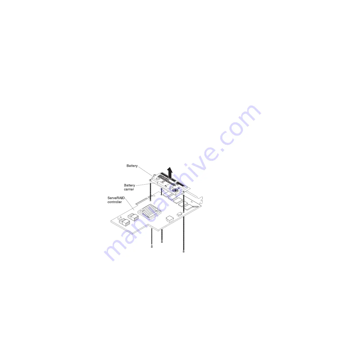
7. If you are instructed to return the ServeRAID controller battery, follow all

packaging instructions, and use any packaging materials for shipping that are
supplied to you.

Installing a ServeRAID controller battery on the remote battery tray

The Intelligent Battery Backup Unit (iBBU) is an optional battery for the ServeRAID
adapter. It is referred to as the

battery

throughout this section. You must purchase

the remote battery cable and install the battery at a distance from the ServeRAID
adapter to avoid overheating.

You can install up to two batteries on the remote battery trays on the PC riser-card
assembly.

To install a ServeRAID controller battery on the remote battery tray, complete the
following steps:

1. If a battery and battery carrier are attached to the SAS controller, remove the

three screws that secure the battery carrier to the ServeRAID controller. Set
the battery and battery carrier aside.

Note:

The illustrations in this document might differ slightly from your

hardware.

2. Install the interposer card on the interposer card connector on the ServeRAID

controller:

a. Remove the interposer card and the loose screw from the bag.

b. Rotate the standoff so that it aligns with the hole in the ServeRAID

controller, and position the interposer card connector over the ServeRAID
controller connector.

172

IBM System x3630 M3 Type 7377: Problem Determination and Service Guide

Содержание x3630 M3 7377

Страница 1: ...IBM System x3630 M3 Type 7377 Problem Determination and Service Guide ...

Страница 2: ......

Страница 3: ...IBM System x3630 M3 Type 7377 Problem Determination and Service Guide ...

Страница 4: ...ntal Notices and User Guide documents on the Documentation CD and the Warranty Information document The most recent version of this document is available at http www ibm com systems support Eighth Edition June 2014 Copyright IBM Corporation 2014 US Government Users Restricted Rights Use duplication or disclosure restricted by GSA ADP Schedule Contract with IBM Corp ...

Страница 5: ...d LEDs 20 Fan board connectors 21 PCI riser card adapter connectors 21 Chapter 3 Diagnostics 23 Diagnostic tools 23 Event logs 24 Viewing event logs from the Setup utility 24 Viewing event logs without restarting the server 24 POST 26 POST error messages 26 Checkout procedure 38 About the checkout procedure 38 Performing the checkout procedure 39 Troubleshooting tables 40 General problems 40 Hard ...

Страница 6: ...oving and replacing Tier 2 CRUs 145 Removing the cover 145 Installing the cover 146 Rotating the optional hot swap rear hard disk drive cage up 147 Rotating the optional hot swap rear hard disk drive cage down 148 Removing the air baffle 148 Installing the air baffle 150 Removing the PCI riser card assembly 150 Installing the PCI riser card assembly 151 Removing a riser card on the PCI riser card ...

Страница 7: ...an optional hot swap SAS SATA rear 2 5 inch hard disk drive cage 210 Installing an optional hot swap SAS SATA rear 2 5 inch hard disk drive cage 214 Removing the fan from the optional rear hard disk drive cage 219 Installing the fan to the optional rear hard disk drive cage 220 Removing a microprocessor and heat sink 221 Installing a microprocessor and heat sink 223 Thermal grease 228 Removing the...

Страница 8: ...ement 264 Industry Canada Class A emission compliance statement 265 Avis de conformité à la réglementation d Industrie Canada 265 Australia and New Zealand Class A statement 265 European Union EMC Directive conformance statement 265 Germany Class A statement 265 Japan VCCI Class A statement 266 Japan Electronics and Information Technology Industries Association JEITA statement 267 Korea Communicat...

Страница 9: ...fety Information Avant d installer ce produit lisez les consignes de sécurité Vor der Installation dieses Produkts die Sicherheitshinweise lesen Prima di installare questo prodotto leggere le Informazioni sulla Sicurezza Les sikkerhetsinformasjonen Safety Information før du installerer dette produktet Antes de instalar este produto leia as Informações sobre Segurança Antes de instalar este product...

Страница 10: ...that the exterior cover is not damaged loose or broken and observe any sharp edges 3 Check the power cord v Make sure that the third wire ground connector is in good condition Use a meter to measure third wire ground continuity for 0 1 ohm or less between the external ground pin and the frame ground v Make sure that the power cord is the correct type as specified in Power cords on page 130 v Make ...

Страница 11: ... the off position v Never assume that power has been disconnected from a circuit Check it to make sure that it has been disconnected v If you have to work on equipment that has exposed electrical circuits observe the following precautions Make sure that another person who is familiar with the power off controls is near you and is available to turn off the power if necessary When you are working wi...

Страница 12: ...y Information document For example if a caution statement is labeled Statement 1 translations for that caution statement are in the Safety Information document under Statement 1 Be sure to read all caution and danger statements in this document before you perform the procedures Read any additional safety information that comes with the server or optional device before you install the device x IBM ...

Страница 13: ...equipment when there is evidence of fire water or structural damage v Disconnect the attached power cords telecommunications systems networks and modems before you open the device covers unless instructed otherwise in the installation and configuration procedures v Connect and disconnect cables as described in the following table when installing moving or opening covers on this product or attached...

Страница 14: ...ttery replace it only with the same module type made by the same manufacturer The battery contains lithium and can explode if not properly used handled or disposed of Do not v Throw or immerse into water v Heat to more than 100 C 212 F v Repair or disassemble Dispose of the battery as required by local ordinances or regulations xii IBM System x3630 M3 Type 7377 Problem Determination and Service Gu...

Страница 15: ...he device v Use of controls or adjustments or performance of procedures other than those specified herein might result in hazardous radiation exposure DANGER Some laser products contain an embedded Class 3A or Class 3B laser diode Note the following Laser radiation when open Do not stare into the beam do not view directly with optical instruments and avoid direct exposure to the beam Class 1 Laser...

Страница 16: ...ice and the power switch on the power supply do not turn off the electrical current supplied to the device The device also might have more than one power cord To remove all electrical current from the device ensure that all power cords are disconnected from the power source 1 2 xiv IBM System x3630 M3 Type 7377 Problem Determination and Service Guide ...

Страница 17: ...present inside any component that has this label attached There are no serviceable parts inside these components If you suspect a problem with one of these parts contact a service technician Statement 12 CAUTION The following label indicates a hot surface nearby Statement 26 CAUTION Do not place any object on top of rack mounted devices Statement 27 Safety xv ...

Страница 18: ...e nearby This server is suitable for use on an IT power distribution system whose maximum phase to phase voltage is 240 V under any distribution fault condition xvi IBM System x3630 M3 Type 7377 Problem Determination and Service Guide ...

Страница 19: ...blems a Document error codes and system board LEDs v System error codes See POST error messages on page 26 for information about error codes v Software or operating system error codes See the documentation for the software or operating system for information about a specific error code See the manufacturer s Web site for documentation v Operator information panel LEDs See Front view on page 10 for...

Страница 20: ...e is part of a cluster solution verify that the latest level of code is supported for the cluster solution before you update the code 1 Determine the existing code levels In DSA click Firmware VPD to view system firmware levels or click Software to view operating system levels 2 Download and install updates of code that is not at the latest level To display a list of available updates for your ser...

Страница 21: ...ck on For information about performing the checkout procedure see Checkout procedure on page 38 If the problem is associated with a specific function for example if a RAID hard disk drive is marked offline in the RAID array see the documentation for the associated controller and management or controlling software to verify that the controller is correctly configured Problem determination informati...

Страница 22: ...oblem remains contact IBM or an approved warranty service provider for assistance with additional problem determination and possible hardware replacement To open an online service request go to http www ibm com support electronic Be prepared to provide information about any error codes and collected data Undocumented problems If you have completed the diagnostic procedure and the problem remains t...

Страница 23: ...ver Related documentation In addition to this document the following documentation also comes with the server v Installation and User s Guide This document is in Portable Document Format PDF on the IBM Documentation CD It provides general information about setting up and cabling the server including information about features and how to configure the server It also contains detailed instructions f...

Страница 24: ...port click System x 3 Under Popular links click Publications lookup 4 From the Product family menu select System x3630 M3 and click Continue Notices and statements in this document The caution and danger statements in this document are also in the multilingual Safety Information document which is on the Documentation CD Each statement is numbered for reference to the corresponding statement in you...

Страница 25: ...the number and type of optional features that are installed and the power management optional features that are in use 2 The sound levels were measured in controlled acoustical environments according to the procedures specified by the American National Standards Institute ANSI S12 10 and ISO 7779 and are reported in accordance with ISO 9296 Actual sound pressure levels in a given location might ex...

Страница 26: ...optional virtual media key v One Intel dual port 10 100 1000 Ethernet controller with Wake on LAN support also support one port as share nic for system management v One serial port provided by the integrated management module IMM v Five Universal Serial Bus USB ports two on front two on rear of server and one internal for an optional USB flash device v One video port on rear of server Note Maximum...

Страница 27: ...iency ac Note You cannot mix high efficiency and non high efficiency power supplies in the server Acoustical noise emissions v Declared sound power idle 6 6 bel v Declared sound power operating 6 6 bel Heat output Approximate heat output v Minimum configuration 762 Btu per hour 223 watts v Maximum configuration 2662 Btu per hour 780 watts EU Regulation 617 2013 Technical Documentation Internationa...

Страница 28: ...mation in this document v ENERGY STAR Servers Version 2 0 Program Requirements ECOVA Generalized Test Protocol for Calculating the Energy Efficiency of Internal Ac Dc and Dc Dc Power Supplies Server controls LEDs and connectors This section describes the controls light emitting diodes LEDs and connectors Front view The following illustration shows the controls connectors and hard disk drive bays o...

Страница 29: ...self has failed Flashing rapidly 4 times per second The server is turned off and is not ready to be turned on The power control button is disabled This will last approximately 20 to 40 seconds Flashing slowly once per second The server is turned off and is ready to be turned on You can press the power control button to turn on the server Lit The server is turned on Fading on and off The server is ...

Страница 30: ...rd to either of these connectors NMI button Press this button to force a nonmaskable interrupt to the microprocessor You might have to use a pen or the end of a straightened paper clip to press the button It allows you to blue screen the server and take a memory dump use this button only when directed by the IBM service support Serial connector Connect a 9 pin serial device to this connector The s...

Страница 31: ...the ac and dc power LEDs are lit For any other combination of LEDs see Power supply LEDs DC power LED Each hot swap power supply has a dc power LED and an ac power LED When the dc power LED is lit it indicates that the power supply is supplying adequate dc power to the system During typical operation both the ac and dc power LEDs are lit For any other combination of LEDs see Power supply LEDs Powe...

Страница 32: ...lace the power supply 2 Make sure that the power cord is connected to a functioning power source This happens only when a second power supply is providing power to the server Off On Off Faulty power supply Replace the power supply Off On On Faulty power supply Replace the power supply On Off Off Power supply not fully seated faulty system board or faulty power supply 1 Reseat the power supply 2 Re...

Страница 33: ... section show the LEDs connectors and jumpers on the internal boards The illustrations might differ slightly from your hardware System board internal connectors The following illustration shows the internal connectors on the system board Chapter 2 Introduction 15 ...

Страница 34: ...System board DIMM connectors The following illustration shows the DIMM connectors on the system board 16 IBM System x3630 M3 Type 7377 Problem Determination and Service Guide ...

Страница 35: ...System board external connectors The following illustration shows the external input output connectors on the system board Chapter 2 Introduction 17 ...

Страница 36: ...y jumper v Pins 1 and 2 Normal default Loads the primary firmware ROM page v Pins 2 and 3 Loads the secondary backup firmware ROM page Notes v If no jumper is present the server responds as if the pins are set to 1 and 2 v Changing the position of the UEFI recovery jumper from pins 1 and 2 to pins 2 and 3 before the server is turned on sets the UEFI recovery process Do not change the jumper pin po...

Страница 37: ...ll power cords and external cables Review the information in Safety on page vii Installation guidelines on page 133 and Handling static sensitive devices on page 135 2 Any system board switch or jumper blocks that are not shown in the illustrations in this document are reserved Chapter 2 Introduction 19 ...

Страница 38: ...ng normally IMM heartbeat When this LED is flashing at a constant rate of every other second it indicates normal operation of the IMM controller When this LED is flashing at a constant rate of every other half second it indicates that the IMM controller is initializing or is not functional Microprocessor mismatch When this LED is lit it indicates that microprocessor 1 is not installed or the micro...

Страница 39: ... Fan 2 connector Fan 3 connector Fan 4 connector Thermal sensor connector Signal connector Power connector Fan 6 connector Fan 5 connector PCI riser card adapter connectors The following illustration shows the connectors on the PCI riser card for user installable PCI adapters Chapter 2 Introduction 21 ...

Страница 40: ...22 IBM System x3630 M3 Type 7377 Problem Determination and Service Guide ...

Страница 41: ...Kernel modules Light path diagnostics status Network interfaces and settings Performance data and details about processes that are running RAID and controller configuration Service processor integrated management module status and configuration System configuration Vital product data and firmware information DSA creates a DSA log which is a chronologically ordered merge of the system event log as ...

Страница 42: ... from one entry to the next use the Up Arrow and Down Arrow keys Some IMM sensors cause assertion events to be logged when their setpoints are reached When a setpoint condition no longer exists a corresponding deassertion event is logged However not all events are assertion type events v Integrated management module IMM event log This log contains a filtered subset of all IMM POST and system manag...

Страница 43: ... the system event log Most recent versions of the Linux operating system come with a current version of IPMItool For an overview of IPMI go to http www ibm com developerworks linux blueprints and click Using Intelligent Platform Management Interface IPMI on IBM Linux platforms Note Changes are made periodically to the IBM Web site The actual procedure might vary slightly from what is described in ...

Страница 44: ...r more information see Viewing event logs from the Setup utility on page 24 POST When you turn on the server it performs a series of tests to check the operation of the server components and some optional devices in the server This series of tests is called the power on self test or POST This server does not use beep codes for server status If a power on password is set you must type the password ...

Страница 45: ... Trained service technician only Replace the following components one at a time in the order shown restarting the server each time a Microprocessor 1 b Microprocessor 2 c System board 0011000 Invalid microprocessor type 1 Update the system firmware see Updating the firmware on page 233 2 Trained service technician only Remove and replace the affected microprocessor error LED is lit with a supporte...

Страница 46: ...d microprocessor specifications 2 Trained service technician only Remove and replace one of the microprocessors so that they both match 0018005 Microprocessors have mismatched number of COREs 1 Run the Setup utility and select System Information System Summary Processor Details to view the microprocessor information to compare the installed microprocessor specifications 2 Trained service technicia...

Страница 47: ...time you install or remove a DIMM you must disconnect the server from the power source then wait 10 seconds before restarting the server 1 Check the IBM support website for an applicable retain tip or firmware update that applies to this memory error 2 Manually re enable all affected DIMMs if the server firmware version is older than UEFI v1 10 If the server firmware version is UEFI v1 10 or newer...

Страница 48: ... a memory module on page 162 3 Make sure that the DIMMs match and are installed in the correct sequence see Installing a memory module on page 162 4 Trained service technician only Replace the microprocessor that controls the failing DIMMs see Removing a microprocessor and heat sink on page 221 and Installing a microprocessor and heat sink on page 223 5 Trained service technician only Replace the ...

Страница 49: ...e affected DIMM 4 Trained service technician only If the problem occurs on the same DIMM connector check the DIMM connector If the connector contains any foreign material or is damaged replace the system board see Removing the system board on page 228 and Installing the system board on page 230 5 Trained service technician only Remove the affected microprocessor and check the microprocessor socket...

Страница 50: ...the problem occurs on the same DIMM connector check the DIMM connector If the connector contains any foreign material or is damaged replace the system board see Removing the system board on page 228 and Installing the system board on page 230 6 Trained service technician only Remove the affected microprocessor and check the microprocessor socket pins for any damaged pins If a damage is found repla...

Страница 51: ...ed DIMM failure events 0068002 CMOS battery cleared 1 Reseat the battery 2 Clear the CMOS memory see System board jumpers on page 18 3 Replace the following components one at a time in the order shown restarting the server each time a Battery b Trained service technician only System board 2011001 PCI X SERR 1 Check the PCI error LEDs 2 Reseat all affected adapters and riser cards 3 Update the PCI ...

Страница 52: ... then PCI ROM Control Execution to disable the ROM of adapters in the PCI slots v Select Devices and I O Ports to disable any of the integrated devices 4 Replace the following components one at a time in the order shown restarting the server each time a Each adapter b Trained service technician only System board 3xx0007 xx can be 00 19 Firmware fault detected system halted 1 Recover the server fir...

Страница 53: ...n restarting the server each time a Battery b Failing device if the device is a FRU then it must be reseated by a trained service technician only 4 Replace the following components one at a time in the order shown restarting the server each time a Battery b Failing device if the device is a FRU then it must be replaced by a trained service technician only c Trained service technician only System b...

Страница 54: ...from the server and then reconnect the server to power and restart it 2 Run the Setup utility and select Save Settings 3 Update the IMM firmware 3808004 IMM system event log full v When out of band use the IMM Web interface or IPMItool to clear the logs from the operating system v When using the local console 1 Run the Setup utility 2 Select System Event Log 3 Select Clear System Event Log 4 Resta...

Страница 55: ...only Replace the system board 3818006 Opposite bank CRTM capsule signature invalid 1 Switch the server firmware bank to the backup bank see Starting the backup server firmware on page 240 2 Run the Setup utility select Load Default Settings and save the settings 3 Switch the bank back to the primary bank 4 Trained service technician only Replace the system board 3818007 CRTM update capsule signatu...

Страница 56: ...programs you must determine whether the failing server is part of a shared hard disk drive cluster two or more servers sharing external storage devices If it is part of a cluster you can run all diagnostic programs except the ones that test the storage unit that is a hard disk drive in the storage unit or the storage adapter that is attached to the storage unit The failing server might be part of ...

Страница 57: ...er serverproven compat us d Make sure the server is cabled correctly e Check all cables and power cords f Set all display controls to the middle positions g Turn on all external devices h Turn on the server If the server does not start see Troubleshooting tables on page 40 i Check the system error LED on the operator information panel If it is flashing check the light path diagnostics LEDs see Sys...

Страница 58: ...receded by Trained service technician only that step must be performed only by a trained service technician v Go to the IBM support Web site at http www ibm com systems support to check for technical information hints tips and new device drivers or to submit a request for information Symptom Action A cover thumbscrew is broken an LED is not working or a similar problem has occurred If the part is ...

Страница 59: ... the LEDs remains the same go to step 4 If the activity of the LEDs changes return to step 1 4 Make sure that the hard disk drive backplane is correctly seated When it is correctly seated the drive assemblies correctly connect to the backplane without bowing or causing movement of the backplane 5 Move the hard disk drives to different bays to determine if the drive or the backplane is not function...

Страница 60: ...and observe the activity of the hard disk drive LEDs 2 See Problem determination tips on page 122 Hypervisor problems v Follow the suggested actions in the order in which they are listed in the Action column until the problem is solved v See Chapter 4 Parts listing Type 7377 server on page 125 to determine which components are customer replaceable units CRU and which components are field replaceab...

Страница 61: ...system logs 5 Contact your operating system vendor to set up any available tools that are capable of monitoring the server 6 If an error occurs run the DSA program and forward the results to IBM service and support for analysis 7 See Solving undetermined problems on page 121 The server resets restarts occasionally 1 If the reset occurs during POST and the POST watchdog timer is enabled click Advan...

Страница 62: ...rver and the monitor are turned on 4 Move the keyboard cable to a different USB connector 5 Replace the following components one at a time in the order shown restarting the server each time a Keyboard b Only if the problem occurred with a front USB connector Internal USB cable front USB connector assembly or USB board c Trained service technician only System board The USB mouse or USB pointing dev...

Страница 63: ... for the discrepancy v The memory modules are seated correctly v You have installed the correct type of memory v If you changed the memory you updated the memory configuration in the Setup utility v All banks of memory are enabled The server might have automatically disabled a memory bank when it detected a problem or a memory bank might have been manually disabled v There is no memory mismatch wh...

Страница 64: ...restarting the server 1 Reseat the DIMMs then restart the server 2 Remove the highest numbered DIMM of those that are identified and replace it with an identical known good DIMM then restart the server Repeat as necessary If the failures continue after all identified DIMMs are replaced go to step 4 3 Return the removed DIMMs one at a time to their original connectors restarting the server after ea...

Страница 65: ...order shown restarting the server each time v Microprocessors v System board Monitor or video problems Some IBM monitors have their own self tests If you suspect a problem with your monitor see the documentation that comes with the monitor for instructions for testing and adjusting the monitor If you cannot diagnose the problem call for service v Follow the suggested actions in the order in which ...

Страница 66: ...e adjusted correctly 4 Make sure that the correct server is controlling the monitor if applicable 5 Make sure that damaged server firmware is not affecting the video see Recovering the server firmware on page 89 for information about recovering from server firmware failure 6 Observe the checkpoint LEDs on the light path diagnostics panel if the codes are changing go to the next step 7 Replace the ...

Страница 67: ...lights and other monitors can cause screen jitter or wavy unreadable rolling or distorted screen images If this happens turn off the monitor Attention Moving a color monitor while it is turned on might cause screen discoloration Move the device and the monitor at least 305 mm 12 in apart and turn on the monitor Notes a To prevent diskette drive read write errors make sure that the distance between...

Страница 68: ...tp www ibm com servers eserver serverproven compat us v You followed the installation instructions that came with the device and the device is installed correctly v You have not loosened any other installed devices or cables v You updated the configuration information in the Setup utility Whenever memory or any other device is changed you must update the configuration 2 Reseat the device that you ...

Страница 69: ...ror LED on the front panel turns on v The type of memory that is installed is correct v The microprocessors are installed in the correct sequence v The fan power cable is correctly connected to the fan board and the power supply paddle card 2 Make sure that the power control button and the reset button are working correctly a Disconnect the server power cords b Reseat the operator information pane...

Страница 70: ...ect connector see Rear view on page 12 2 Reseat the following components a Failing serial device b Serial cable 3 Replace the following components one at a time in the order shown restarting the server each time a Failing serial device b Serial cable c Trained service technician only System board ServerGuide problems v Follow the suggested actions in the order in which they are listed in the Actio...

Страница 71: ...ted Microsoft Windows operating systems The operating system cannot be installed the option is not available Make sure that the server supports the operating system If it does no logical drive is defined RAID servers Run the ServerGuide program and make sure that setup is complete Software problems v Follow the suggested actions in the order in which they are listed in the Action column until the ...

Страница 72: ... time a USB device b Only if the problem occurred with a front USB connector Internal USB cable front USB connector assembly or USB board Video problems See Monitor or video problems on page 47 Error LEDs The system board has error LEDs that will help to locate the source of the error see System board LEDs on page 20 Run the diagnostic programs to find out the cause of the error see IBM Dynamic Sy...

Страница 73: ... the order in which they are listed in the Action column until the problem is solved v See Chapter 4 Parts listing Type 7377 server on page 125 to determine which components are customer replaceable units CRU and which components are field replaceable units FRU v If an action step is preceded by Trained service technician only that step must be performed only by a trained service technician Compon...

Страница 74: ...rocessor 1 is installed 2 Check the microprocessors are compatible with each other see Installing a microprocessor and heat sink on page 223 for additional information about microprocessor requirements and use the Setup utility and select System Information System Summary Processor Details to verify the microprocessors information 3 Trained service technician only Replace the incompatible micropro...

Страница 75: ...e to the server complete the following steps a Trained service technician only use the IMM recovery jumper to recover the firmware see System board jumpers on page 18 b Trained service technician only replace the system board Note Make sure the technician refreshes the VPD PCI error LEDs An error has occurred on a PCI bus or on the system board An additional LED is lit next to a failing PCI slot 1...

Страница 76: ...C DC AC power LED DC power LED Power supply error LED AC DC The following table describes the problems that are indicated by various combinations of the power supply LEDs and suggested actions to correct the detected problems 58 IBM System x3630 M3 Type 7377 Problem Determination and Service Guide ...

Страница 77: ...al condition when no ac power is present Off Off On No ac power to the server or a problem with the ac power source and the power supply had detected an internal problem 1 Replace the power supply 2 Make sure that the power cord is connected to a functioning power source This happens only when a second power supply is providing power to the server Off On Off Faulty power supply Replace the power s...

Страница 78: ...0008 lndocid SERV DSA or complete the following steps Note Changes are made periodically to the IBM Web site The actual procedure might vary slightly from what is described in this document 1 Go to http www ibm com systems support 2 Under IBM Systems support click System x 3 Under Related downloads click Dynamic System Analysis DSA DSA editions Three editions of Dynamic System Analysis are availab...

Страница 79: ...terface that you can use to specify which diagnostics to run and to view the diagnostic and data collection results If you are unable to start the server or if you need comprehensive diagnostics use DSA Preboot DSA messages The following table describes the messages that DSA might generate and suggested actions to correct the detected problems In a message number x can be any numeral or letter How...

Страница 80: ...ain 8 If the failure remains go to the IBM Web site for more troubleshooting information at http www ibm com systems support supportsite wss docdisplay brandind 5000008 lndocid SERV CALL 089 802 xxx CPU CPU Stress Test Aborted System resource availability error 1 Turn off and restart the system 2 Make sure that the DSA code is at the latest level For the latest level of DSA code go to http www ibm...

Страница 81: ...33 5 Run the test again 6 Turn off and restart the system if necessary to recover from a hung state 7 Run the test again 8 If the failure remains go to the IBM Web site for more troubleshooting information at http www ibm com systems support supportsite wss docdisplay brandind 5000008 lndocid SERV CALL 166 801 xxx IMM IMM I2C Test Aborted IMM I2C test stopped the IMM returned an incorrect response...

Страница 82: ...e diagnostic event log in the Firmware VPD section for this component For more information see Updating the firmware on page 233 6 Run the test again 7 If the failure remains go to the IBM Web site for more troubleshooting information at http www ibm com systems support supportsite wss docdisplay brandind 5000008 lndocid SERV CALL 166 803 xxx IMM IMM I2C Test Aborted IMM I2C test stopped the node ...

Страница 83: ... the diagnostic event log in the Firmware VPD section for this component For more information see Updating the firmware on page 233 6 Run the test again 7 If the failure remains go to the IBM Web site for more troubleshooting information at http www ibm com systems support supportsite wss docdisplay brandind 5000008 lndocid SERV CALL 166 805 xxx IMM IMM I2C Test Aborted IMM I2C test stopped invali...

Страница 84: ...e diagnostic event log in the Firmware VPD section for this component For more information see Updating the firmware on page 233 6 Run the test again 7 If the failure remains go to the IBM Web site for more troubleshooting information at http www ibm com systems support supportsite wss docdisplay brandind 5000008 lndocid SERV CALL 166 807 xxx IMM IMM I2C Test Aborted IMM I2C test stopped out of sp...

Страница 85: ...e level is shown in the diagnostic event log in the Firmware VPD section for this component For more information see Updating the firmware on page 233 6 Run the test again 7 If the failure remains go to the IBM Web site for more troubleshooting information at http www ibm com systems support supportsite wss docdisplay brandind 5000008 lndocid SERV CALL 166 809 xxx IMM IMM I2C Test Aborted IMM I2C ...

Страница 86: ... log in the Firmware VPD section for this component For more information see Updating the firmware on page 233 6 Run the test again 7 If the failure remains go to the IBM Web site for more troubleshooting information at http www ibm com systems support supportsite wss docdisplay brandind 5000008 lndocid SERV CALL 166 811 xxx IMM IMM I2C Test Aborted IMM I2C test stopped request data field length l...

Страница 87: ...the diagnostic event log in the Firmware VPD section for this component For more information see Updating the firmware on page 233 6 Run the test again 7 If the failure remains go to the IBM Web site for more troubleshooting information at http www ibm com systems support supportsite wss docdisplay brandind 5000008 lndocid SERV CALL 166 813 xxx IMM IMM I2C Test Aborted IMM I2C test stopped cannot ...

Страница 88: ...gnostic event log in the Firmware VPD section for this component For more information see Updating the firmware on page 233 6 Run the test again 7 If the failure remains go to the IBM Web site for more troubleshooting information at http www ibm com systems support supportsite wss docdisplay brandind 5000008 lndocid SERV CALL 166 815 xxx IMM IMM I2C Test Aborted IMM I2C test stopped invalid data f...

Страница 89: ...re level is shown in the diagnostic event log in the Firmware VPD section for this component For more information see Updating the firmware on page 233 6 Run the test again 7 If the failure remains go to the IBM Web site for more troubleshooting information at http www ibm com systems support supportsite wss docdisplay brandind 5000008 lndocid SERV CALL 166 817 xxx IMM IMM I2C Test Aborted IMM I2C...

Страница 90: ...mware VPD section for this component For more information see Updating the firmware on page 233 6 Run the test again 7 If the failure remains go to the IBM Web site for more troubleshooting information at http www ibm com systems support supportsite wss docdisplay brandind 5000008 lndocid SERV CALL 166 819 xxx IMM IMM I2C Test Aborted IMM I2C test stopped a command response could not be provided t...

Страница 91: ...in the Firmware VPD section for this component For more information see Updating the firmware on page 233 6 Run the test again 7 If the failure remains go to the IBM Web site for more troubleshooting information at http www ibm com systems support supportsite wss docdisplay brandind 5000008 lndocid SERV CALL 166 821 xxx IMM IMM I2C Test Aborted IMM I2C test stopped a command response could not be ...

Страница 92: ...n the Firmware VPD section for this component For more information see Updating the firmware on page 233 6 Run the test again 7 If the failure remains go to the IBM Web site for more troubleshooting information at http www ibm com systems support supportsite wss docdisplay brandind 5000008 lndocid SERV CALL 166 823 xxx IMM IMM I2C Test Aborted IMM I2C test stopped cannot execute the command insuff...

Страница 93: ...ystem and disconnect it from the power source You must disconnect the system from ac power to reset the IMM 2 After 45 seconds reconnect the system to the power source and turn on the system 3 Run the test again 4 Make sure that the DSA code is at the latest level For the latest level of DSA code go to http www ibm com support docview wss uid psg1SERV DSA 5 Make sure that the IMM firmware is at th...

Страница 94: ...nect the system to the power source and turn on the system 3 Run the test again 4 Make sure that the DSA code is at the latest level For the latest level of DSA code go to http www ibm com support docview wss uid psg1SERV DSA 5 Make sure that the IMM firmware is at the latest level The installed firmware level is shown in the diagnostic event log in the Firmware VPD section for this component For ...

Страница 95: ...he test again 4 Make sure that the DSA code is at the latest level For the latest level of DSA code go to http www ibm com support docview wss uid psg1SERV DSA 5 Make sure that the IMM firmware is at the latest level The installed firmware level is shown in the diagnostic event log in the Firmware VPD section for this component For more information see Updating the firmware on page 233 6 Run the t...

Страница 96: ...t docview wss uid psg1SERV DSA 5 Make sure that the IMM firmware is at the latest level The installed firmware level is shown in the diagnostic event log in the Firmware VPD section for this component For more information see Updating the firmware on page 233 6 Run the test again 7 Disconnect the system from the power source 8 Replace the DIMMs one at a time and run the test again after replacing ...

Страница 97: ...test again 4 Make sure that the DSA code is at the latest level For the latest level of DSA code go to http www ibm com support docview wss uid psg1SERV DSA 5 Make sure that the IMM firmware is at the latest level The installed firmware level is shown in the diagnostic event log in the Firmware VPD section for this component For more information see Updating the firmware on page 233 6 Run the test...

Страница 98: ...em 3 Run the test again 4 Make sure that the DSA code is at the latest level For the latest level of DSA code go to http www ibm com support docview wss uid psg1SERV DSA 5 Make sure that the IMM firmware is at the latest level The installed firmware level is shown in the diagnostic event log in the Firmware VPD section for this component For more information see Updating the firmware on page 233 6...

Страница 99: ...level The installed firmware level is shown in the diagnostic event log in the Firmware VPD section for this component For more information see Updating the firmware on page 233 6 Run the test again 7 Turn off the system and disconnect it from the power source 8 Trained service technician only Reseat the system board 9 Reconnect the system to the power source and turn on the system 10 Run the test...

Страница 100: ...port supportsite wss docdisplay brandind 5000008 lndocid SERV CALL 201 803 xxx Memory Memory Test Aborted Test canceled could not enable the processor cache 1 Turn off and restart the system 2 Run the test again 3 Make sure that the server firmware is at the latest level The installed firmware level is shown in the diagnostic event log in the Firmware VPD section for this component For more inform...

Страница 101: ...te wss docdisplay brandind 5000008 lndocid SERV CALL 201 806 xxx Memory Memory Test Aborted Test canceled the memory controller fast scrub operation was not completed 1 Turn off and restart the system 2 Run the test again 3 Make sure that the server firmware is at the latest level The installed firmware level is shown in the diagnostic event log in the Firmware VPD section for this component For m...

Страница 102: ...the system 2 Run the test again 3 Make sure that the DSA code is at the latest level For the latest level of DSA code go to http www ibm com support docview wss uid psg1SERV DSA 4 Make sure that the server firmware is at the latest level The installed firmware level is shown in the diagnostic event log in the Firmware VPD section for this component For more information see Updating the firmware on...

Страница 103: ...mation see Updating the firmware on page 233 6 Run the test again 7 Replace the failing DIMMs 8 Re enable all memory in the Setup utility see Using the Setup utility on page 235 9 Run the test again 10 Replace the failing DIMM 11 If the failure remains go to the IBM Web site for more troubleshooting information at http www ibm com systems support supportsite wss docdisplay brandind 5000008 lndocid...

Страница 104: ... http www ibm com systems support supportsite wss docdisplay brandind 5000008 lndocid SERV CALL 202 901 xxx Memory Memory Stress Test Failed Test failure 1 Run the standard memory test to validate all memory 2 Make sure that the DSA code is at the latest level For the latest level of DSA code go to http www ibm com support docview wss uid psg1SERV DSA 3 Turn off the system and disconnect it from p...

Страница 105: ...are is at the latest level The installed firmware level is shown in the diagnostic event log in the Firmware VPD section for this component For more information see Updating the firmware on page 233 2 Run the test again 3 Replace the component that is causing the error If the error is caused by an adapter replace the adapter Check the PCI Information and Network Settings information in the DSA eve...

Страница 106: ...000008 lndocid SERV CALL Tape alert flags If a tape drive is installed in the server go to http www ibm com systems support supportsite wss docdisplay lndocid MIGR 5079217 brandind 5000008 for the Tape Storage Products Problem Determination and Service Guide This document describes troubleshooting and problem determination information for your tape drive Tape alert flags are numbered 1 through 64 ...

Страница 107: ...e code If the server firmware has become corrupted such as from a power failure during an update you can recover the server firmware in one of two ways v In band method Recover server firmware using either the boot block jumper Automated Boot Recovery and a server Firmware Update Package Service Pack v Out of band method Use the IMM Web Interface to update the firmware using the latest server firm...

Страница 108: ...per block JP3 see Removing an adapter from the PCI riser card assembly on page 156 6 Move the UEFI boot recovery jumper block JP3 from pins 1 and 2 to pins 2 and 3 to enable the UEFI recovery mode 7 Reinstall any adapter that you removed before see Installing an adapter on the PCI riser card assembly on page 157 8 Reinstall the server cover see Installing the cover on page 146 9 Reconnect all powe...

Страница 109: ...tery see Removing the system battery on page 142 22 Leave the system battery out of the server for approximately 5 to 15 minutes 23 Reinstall the system battery see Installing the system battery on page 143 24 Reinstall the server cover see Installing the cover on page 146 then reconnect all power cords 25 Restart the server The power on self test POST starts 26 If these recovery efforts fail cont...

Страница 110: ...er of the following ways v The server restarts automatically and attempts POST again v The server hangs and you must manually restart the server for the server to attempt POST again After a specified number of consecutive attempts automatic or manual the Nx boot failure feature causes the server to revert to the default UEFI configuration and start the Setup utility so that you can make the necess...

Страница 111: ...listing Type 7377 server on page 125 to determine which components are customer replaceable units CRU and which components are field replaceable units FRU v If an action step is preceded by Trained service technician only that step must be performed only by a trained service technician Message Severity Description Action 1 Platform Watchdog Timer expired for 2 1 OS Watchdog or Loader Watchdog 2 OS...

Страница 112: ...4 Check for a UEFI firmware update Important Some cluster solutions require specific code levels or coordinated code updates If the device is part of a cluster solution verify that the latest level of code is supported for the cluster solution before you update the code 5 Make sure that the two microprocessors are matching see Installing a microprocessor and heat sink on page 223 for information a...

Страница 113: ...are compatible with each other see Installing a microprocessor and heat sink on page 223 for information about microprocessor requirements 3 Trained service technician only Reseat microprocessor n 4 Trained service technician only Replace microprocessor n n microprocessor number Attempting to 1 server 2 by user 3 1 Power Up Power Down Power Cycle or Reset 2 IBM_ComputerSystem ElementName 3 user ID...

Страница 114: ...rk that can assign an IP address to the IMM ENET 0 DHCP HSTN 1 DN 2 IP 3 SN 4 GW 5 DNS1 6 1 CIM_DNSProtocolEndpoint Hostname 2 CIM_DNSProtocolEndpoint DomainName 3 CIM_IPProtocolEndpoint IPv4Address 4 CIM_IPProtocolEndpoint SubnetMask 5 IP address xxx xxx xxx xxx 6 IP address xxx xxx xxx xxx Info The DHCP server has assigned an IMM IP address and configuration No action information only ENET 0 IP ...

Страница 115: ...rmation only Ethernet Duplex setting modified from 1 to 2 by user 3 1 CIM_EthernetPort Network Addresses 2 CIM_EthernetPort Network Addresses 3 user ID Info A user has modified the Ethernet port MAC address setting No action information only Ethernet interface 1 by user 2 1 CIM_EthernetPort Enabled State 2 user ID Info A user has enabled the Ethernet interface No action information only Ethernet l...

Страница 116: ...own restarting the server each time a Hard disk drive b Cable from the system board to the backplane c Hard disk drive backplane Fault in slot System board on system 1 1 CIM_ComputerSystem ElementName Error A PCI slot error has occurred 1 Check the riser card LEDs 2 Reseat the affected adapters and riser card 3 Update the server and adapter firmware UEFI and IMM Important Some cluster solutions re...

Страница 117: ...ion only Hostname set to 1 by user 2 1 CIM_DNSProtocolEndpoint Hostname 2 user ID Info A user has modified the host name of the IMM No action information only IMM clock has been set from NTP server 1 1 IBM_NTPService Element Name Info The IMM clock has been set to the date and time that is provided by the Network Time Protocol server No action information only IMM Configuration 1 restored from a c...

Страница 118: ...nt SubnetMask 2 CIM_StaticIPAssignment SettingData SubnetMask 3 user ID Info A user has modified the IP subnet mask of the IMM No action information only LAN Ethernet 0 interface is no longer active Info The IMM Ethernet interface has been disabled No action information only LAN Ethernet 0 interface is now active Info The IMM Ethernet interface has been enabled No action information only Memory DI...

Страница 119: ...IMMs as indicated by the error LEDs on the system board or the event logs to a different memory channel or microprocessor see Installing a memory module on page 162 3 If the error still occurs on the same DIMM replace the affected DIMM 4 Trained service technician only If the problem occurs on the same DIMM connector check the DIMM connector If the connector contains any foreign material or is dam...

Страница 120: ...ror LEDs on the system board or the event logs to a different memory channel or microprocessor see Installing a memory module on page 162 for memory population 3 If the error still occurs on the same DIMM replace the affected DIMM 4 Trained service technician only If the problem occurs on the same DIMM connector check the DIMM connector If the connector contains any foreign material or is damaged ...

Страница 121: ... as indicated by the error LEDs on the system board or the event logs to a different memory channel or microprocessor see Installing a memory module on page 162 for memory population 3 If the error still occurs on the same DIMM replace the affected DIMM 4 Trained service technician only If the problem occurs on the same DIMM connector check the DIMM connector If the connector contains any foreign ...

Страница 122: ...s memory error 2 Manually re enable all affected DIMMs if the server firmware version is older than UEFI v1 10 If the server firmware version is UEFI v1 10 or newer disconnect and reconnect the server to the power source and restart the server 3 Swap the affected DIMMs as indicated by the error LEDs on the system board or the event logs to a different memory channel or microprocessor see Installin...

Страница 123: ...ained service technician Message Severity Description Action Memory uncorrectable error detected for DIMM All DIMMs on Memory Subsystem All DIMMs Error A memory uncorrectable error has occurred 6 Trained service technician only Remove the affected microprocessor and check the microprocessor socket pins for any damaged pins If a damage is found replace the system board see Removing the system board...

Страница 124: ...memory error 2 Manually re enable all affected DIMMs if the server firmware version is older than UEFI v1 10 If the server firmware version is UEFI v1 10 or newer disconnect and reconnect the server to the power source and restart the server 3 Swap the affected DIMMs as indicated by the error LEDs on the system board or the event logs to a different memory channel or microprocessor see Installing ...

Страница 125: ...vice technician Message Severity Description Action Memory uncorrectable error detected for DIMM n Status on Memory Subsystem DIMM n Status n DIMM number Error A memory uncorrectable error has occurred 6 Trained service technician only Remove the affected microprocessor and check the microprocessor socket pins for any damaged pins If a damage is found replace the system board see Removing the syst...

Страница 126: ...mory error 2 Manually re enable all affected DIMMs if the server firmware version is older than UEFI v1 10 If the server firmware version is UEFI v1 10 or newer disconnect and reconnect the server to the power source and restart the server 3 Swap the affected DIMMs as indicated by the error LEDs on the system board or the event logs to a different memory channel or microprocessor see Installing a ...

Страница 127: ...maged pins If a damage is found replace the system board see Removing the system board on page 228 and Installing the system board on page 230 7 Trained Service technician only Replace the affected microprocessor see Removing a microprocessor and heat sink on page 221 and Installing a microprocessor and heat sink on page 223 Memory DIMM disabled for All DIMMs on Memory Subsystem All DIMMs Info DIM...

Страница 128: ...If no memory fault is recorded in the logs and no DIMM connector error LED is lit you can re enable the DIMM through the Setup utility or the Advanced Settings Utility ASU Memory DIMM disabled for DIMM n Status on Memory Subsystem DIMM n Status n DIMM number Info DIMM disabled 1 Make sure the DIMM is installed correctly see Installing a memory module on page 162 2 If the DIMM was disabled because ...

Страница 129: ...nsor Planar 12V going low lower critical has asserted Error A lower critical sensor going low has asserted Trained service technician only Replace the system board Note Make sure the technician refreshes the VPD Numeric sensor Planar 3 3V going high upper critical has asserted Error An upper critical sensor going high has asserted Trained service technician only Replace the system board Note Make ...

Страница 130: ...roring in the Setup utility Remote access attempt failed Invalid userid or password received Userid is 1 from TELNET client at IP address 2 1 user ID 2 IP address xxx xxx xxx xxx Error A user has attempted to log in from a Telnet session by using an invalid login ID or password 1 Make sure that the correct login ID and password are being used 2 Have the system administrator reset the login ID or p...

Страница 131: ...ser has exceeded the maximum number of unsuccessful login attempts from a Web browser and has been prevented from logging in for the lockout period 1 Make sure that the correct login ID and password are being used 2 Have the system administrator reset the login ID or password Sensor CPU n OverTemp has transitioned to critical from a less severe state n microprocessor number Error A sensor has chan...

Страница 132: ...ate from a less severe state Replace the corresponding power supply SSL data in the IMM configuration data is invalid Clearing configuration data region and disabling SSL H25 Error There is a problem with the certificate that has been imported into the IMM The imported certificate must contain a public key that corresponds to the key pair that was previously generated through the Generate a New Ke...

Страница 133: ...ollowing components a Hard disk drive b Cable from the system board to the backplane 3 Replace the following components one at a time in the order shown restarting the server each time a Hard disk drive b Cable from the system board to the backplane c Hard disk drive backplane n hard disk drive number The Drive n Status has been removed from unit Drive 0 Status n hard disk drive number Error A dri...

Страница 134: ...r and heat sink on page 223 for information about microprocessor requirements 2 Trained service technician only Replace the incompatible microprocessor The Processor CPU n Status has Failed with FRB1 BIST condition n microprocessor number Error A processor failed FRB1 BIST condition has occurred 1 Check for a UEFI firmware update Important Some cluster solutions require specific code levels or coo...

Страница 135: ...tant Some cluster solutions require specific code levels or coordinated code updates If the device is part of a cluster solution verify that the latest level of code is supported for the cluster solution before you update the code 2 Run the DSA program for the hard disk drives and other I O devices 3 Trained service technician only Replace microprocessor n n microprocessor number The Processor CPU...

Страница 136: ...er solutions require specific code levels or coordinated code updates If the device is part of a cluster solution verify that the latest level of code is supported for the cluster solution before you update the code 3 Trained service technician only Replace the system board Note Make sure the technician refreshes the VPD The System 1 encountered a POST Error 1 CIM_ComputerSystem ElementName Error ...

Страница 137: ...installed operating system 6 Update the IMM firmware Important Some cluster solutions require specific code levels or coordinated code updates If the device is part of a cluster solution verify that the latest level of code is supported for the cluster solution before you update the code Watchdog 1 Screen Capture Occurred 1 OS Watchdog or Loader Watchdog Error An operating system error has occurre...

Страница 138: ... interface see Logging on to the Web interface on page 245 b If a log indicates that the power configuration is invalid make sure that both power supplies installed in the server are of the same type 5 Remove the adapters and disconnect the cables and power cords to all internal and external devices until the server is at the minimum configuration that is required for the server to start see Solvi...

Страница 139: ...d server are using the same protocol If the Ethernet controller still cannot connect to the network but the hardware appears to be working the network administrator must investigate other possible causes of the error Solving undetermined problems If the diagnostic tests did not diagnose the failure or if the server is inoperative use the information in this section If you suspect that a software p...

Страница 140: ... IBM v Machine type and model v Microprocessor and hard disk upgrades v Failure symptom Does the server fail the diagnostics tests What occurs When Where Does the failure occur on a single server or on multiple servers Is the failure repeatable Has this configuration ever worked What changes if any were made before the configuration failed Is this the original reported failure v Diagnostics progra...

Страница 141: ...v Operating system control file setup See Appendix A Getting help and technical assistance on page 259 for information about calling IBM for service Chapter 3 Diagnostics 123 ...

Страница 142: ...124 IBM System x3630 M3 Type 7377 Problem Determination and Service Guide ...

Страница 143: ...ur responsibility If IBM acquires or installs a consumable part at your request you will be charged for the service v Tier 1 customer replaceable unit CRU Replacement of Tier 1 CRUs is your responsibility If IBM installs a Tier 1 CRU at your request you will be charged for the installation v Tier 2 customer replaceable unit You may install a Tier 2 CRU yourself or request IBM to install it at no a...

Страница 144: ...d disk 69Y5273 2 ServeRAID M1015 SAS SATA adapter models 32x and 42x 46M0861 2 ServeRAID M5015 SAS SATA adapter battery not included models 62x and E2Y 46M0851 2 ServeRAID M5014 SAS SATA adapter model 22x 46M0918 3 PCI riser card assembly 69Y1053 4 Heat sink 69Y4249 5 Microprocessor Intel Xeon L5609 1 86 GHz 12 MB 40 W quad core 69Y0783 5 Microprocessor Intel Xeon E5603 1 60 GHz 4 MB 80 W quad cor...

Страница 145: ...E5630 2 53 GHz 12 MB 80 W quad core model 52x 49Y7052 5 Microprocessor Intel Xeon E5649 2 53 GHz 12 MB 80 W 6 core model 52x 81Y5955 5 Microprocessor Intel Xeon E5640 2 66 GHz 12 MB 80 W quad core 49Y7051 5 Microprocessor Intel Xeon X5650 2 66 GHz 12 MB 95 W 6 core model 62x 64x 49Y7040 5 Microprocessor Intel Xeon X5660 2 80 GHz 12 MB 95 W 6 core 49Y7039 5 Microprocessor Intel Xeon X5670 2 93 GHz ...

Страница 146: ...k drive hot swap 3 5 inch 250 GB SATA 40K6889 13a Hard disk drive hot swap 3 5 inch 300 GB SAS 14 K 44W2235 13a Hard disk drive hot swap 3 5 inch 450 GB SAS 15 K 44W2240 13a Hard disk drive hot swap 3 5 inch 600 GB SAS 15 K 44W2245 13a Hard disk drive hot swap 600 GB SFF SAS 10 K 49Y2004 13b Hard disk drive hot swap 2 5 inch 146 GB 10 K 42D0633 13b Hard disk drive hot swap 2 5 inch 300 GB 10 K 42D...

Страница 147: ...assembly 69Y1050 Front USB board assembly 69Y1052 Cover front IO assembly 69Y1049 Cover front USB 69Y4534 PCIe riser card 1 x 16 and 1 x 8 69Y4242 PCIe riser card 1 x 4 69Y4243 Cable 24 inch SATA 25R5635 Cable backplane to PDB power 69Y4491 Cable fan power 69Y4211 Cable fan signal 69Y4489 Cable I2 C planar to to hot swap hard disk drive backplane for 2 5 inch hard disk drive model 69Y4495 Cable I2...

Страница 148: ...from the retail store Table 9 Consumable parts Type 7377 Index Description Part number 20 ServeRAID M5000 series battery model 62x 43W4342 To order a consumable part complete the following steps 1 Go to http www ibm com 2 From the Products menu select Upgrades accessories parts 3 Click Obtain maintenance parts then follow the instructions to order the part from the retail store If you need help wi...

Страница 149: ... Czech Republic Dahomey Djibouti Egypt Equatorial Guinea Eritrea Estonia Ethiopia Finland France French Guyana French Polynesia Germany Greece Guadeloupe Guinea Guinea Bissau Hungary Iceland Indonesia Iran Kazakhstan Kyrgyzstan Laos People s Democratic Republic of Latvia Lebanon Lithuania Luxembourg Macedonia former Yugoslav Republic of Madagascar Mali Martinique Mauritania Mauritius Mayotte Moldo...

Страница 150: ...States of America Venezuela 39M5081 110 120 V Antigua and Barbuda Aruba Bahamas Barbados Belize Bermuda Bolivia Caicos Islands Canada Cayman Islands Colombia Costa Rica Cuba Dominican Republic Ecuador El Salvador Guam Guatemala Haiti Honduras Jamaica Mexico Micronesia Federal States of Netherlands Antilles Nicaragua Panama Peru Philippines Saudi Arabia Thailand Taiwan United States of America Vene...

Страница 151: ... the loss of data To avoid this potential problem always use an electrostatic discharge wrist strap or other grounding system when removing or installing a hot swap device v This product is not intended to be connected directly or indirectly by any means whatsoever to interfaces of public telecommunications networks neither to be used in Public Services Network Before you remove or replace a compo...

Страница 152: ...portant data before you make changes to disk drives v Have a small flat blade screwdriver available v To view the error LEDs on the system board and internal components leave the server connected to power v You do not have to turn off the server to install or replace redundant hot swap ac power supplies or hot plug Universal Serial Bus USB devices However you must turn off the server before you pe...

Страница 153: ...ibility of damage from electrostatic discharge observe the following precautions v Limit your movement Movement can cause static electricity to build up around you v The use of a grounding system is recommended For example wear an electrostatic discharge wrist strap if one is available Always use an electrostatic discharge wrist strap or other grounding system when working inside the server with t...

Страница 154: ...al cables make sure that you first connect the signal cable and then the power cable 2 The signal cables are always disconnected first and then the power cable and the hot swap backplane signal cable 3 Make sure the longer signal cable connects to Port 0 and the shorter signal cable connects to Port 1 on the ServeRAID M1015 adapter The following illustration shows the cable routing of the server m...

Страница 155: ...Hot swap backplane power cable Signal cables Hot swap backplane ServeRAID M1015 adapter Hot swap backplane signal cable Port 1 Port 0 Port 0 Port 1 Chapter 5 Removing and replacing server components 137 ...

Страница 156: ...the drive assembly completely from the bay 5 If you are instructed to return the hot swap drive follow all packaging instructions and use any packaging materials for shipping that are supplied to you Installing a hot swap hard disk drive The following notes describe the type of hard disk drives that the server supports and other information that you must consider when you install a drive For a lis...

Страница 157: ...and the green activity LED remains lit during the rebuild process If the amber LED remains lit see Hard disk drive problems on page 40 Note You might have to reconfigure the disk arrays after you install hard disk drives See the RAID documentation on the IBM ServeRAID Support CD for information about RAID controllers Removing a hot swap power supply Important If the server has two power supplies a...

Страница 158: ... server has two power supplies and if any of the power supplies fails the server will not have redundant power and you must replace the power supply immediately Note You cannot mix high efficiency and non high efficiency power supplies in the server Statement 5 CAUTION The power control button on the device and the power switch on the power supply do not turn off the electrical current supplied to...

Страница 159: ...tention latch clicks into place 2 Connect the power cord for the new power supply to the power cord connector on the power supply The following illustration shows the power cord connectors on the back of the server AC DC AC DC Power cord connectors 3 Route the power cord through the power supply handle and through any cable clamps on the rear of the server to prevent the power cord from being acci...

Страница 160: ... or disassemble Dispose of the battery as required by local ordinances or regulations To remove the battery complete the following steps 1 Read the safety information that begins on page vii and Installation guidelines on page 133 2 Follow any special handling and installation instructions that come with the battery 3 Turn off the server and peripheral devices and disconnect the power cord and all...

Страница 161: ...mage the socket on the system board Any damage to the socket may require replacing the system board 9 Dispose of the battery as required by local ordinances or regulations See the IBM Environmental Notices and User s Guide on the IBM Documentation CD for more information Installing the system battery The following notes describe information that you must consider when you replace the system batter...

Страница 162: ...rse into water v Heat to more than 100 C 212 F v Repair or disassemble Dispose of the battery as required by local ordinances or regulations See the IBM Environmental Notices and User s Guide on the IBM Documentation CD for more information To install the replacement battery complete the following steps 1 Follow any special handling and installation instructions that come with the replacement batt...

Страница 163: ...n this document might differ slightly from your hardware Removing the cover To remove the cover complete the following steps 1 Read the safety information that begins on page vii and Installation guidelines on page 133 2 If you are planning to view the error LEDs that are on the system board and components leave the server connected to power and go directly to step 4 3 If you are planning to insta...

Страница 164: ...tions and use any packaging materials for shipping that are supplied to you Installing the cover To install the cover complete the following steps 1 Make sure that all internal cables are correctly routed see Internal cable routing and connectors on page 136 2 Align the cover over the server toward the rear of the server until the cover edges slip into position over the chassis Attention Before sl...

Страница 165: ...ipheral devices and the server Rotating the optional hot swap rear hard disk drive cage up To rotate the optional hot swap hard disk drive cage up complete the following steps 1 3 1 2 1 Read the safety information that begins on page vii and Installation guidelines on page 133 2 Turn off the server and peripheral devices and disconnect all power cords and external cables 3 Remove the cover see Rem...

Страница 166: ...isk drive cage down complete the following steps 3 1 2 3 1 Shift the switch on the rear hard disk drive cage to the unlock position 2 Rotate the cage inward until it sits into place 3 Close the blue latches on the chassis 4 Install the cover see Installing the cover on page 146 5 Reconnect the external cables then reconnect the power cords and turn on the peripheral devices and the server Removing...

Страница 167: ...optional hot swap rear hard disk drive cage up on page 147 5 Grasp the top of the air baffle and lift the air baffle out of the server Attention For proper cooling and airflow replace the air baffle making sure all cables are out of the way before you turn on the server Operating the server with the air baffle removed might damage server components 6 If you are instructed to return the air baffle ...

Страница 168: ...ional hot swap rear hard disk drive cage down on page 148 4 Install the cover see Installing the cover on page 146 5 Reconnect the external cables then reconnect the power cords and turn on the peripheral devices and the server Removing the PCI riser card assembly The server comes with one PCI riser card assembly that contains two PCI Express Gen 2 x16 connectors and one PCI Express x8 connector T...

Страница 169: ...ny packaging materials for shipping that are supplied to you Installing the PCI riser card assembly To install a riser card assembly complete the following steps 1 Reinstall any adapters and reconnect any internal cables you might have removed in other procedures see Internal cable routing and connectors on page 136 2 Connect ServeRAID card signal cables if any 3 Align the PCI riser card assembly ...

Страница 170: ...f the server and peripheral devices and disconnect all power cords and external cables 3 Remove the server cover see Removing the cover on page 145 4 Remove the PCI riser card assembly see Removing the PCI riser card assembly on page 150 5 Remove any adapter on the PCI riser card assembly see Removing an adapter from the PCI riser card assembly on page 156 6 If you are removing PCI riser card 2 th...

Страница 171: ...The following illustration shows how to remove PCI riser card 2 from the PCI riser card assembly Chapter 5 Removing and replacing server components 153 ...

Страница 172: ...he following steps 1 Touch the static protective package that contains the new PCI riser card to any unpainted metal surface on the server Then remove the ServeRAID controller from the package 2 Align the screw holes on the PCI riser card with the screw holes on the PCI riser card assembly Make sure the locating pins engages the PCI riser card The following illustration shows how to install PCI ri...

Страница 173: ...The following illustration shows how to install PCI riser card 2 on the PCI riser card assembly Chapter 5 Removing and replacing server components 155 ...

Страница 174: ... external cables then reconnect the power cords and turn on the peripheral devices and the server Removing an adapter from the PCI riser card assembly This topic describes removing an adapter from a PCI expansion slot in the PCI riser card assembly These instructions apply to PCI adapters such as video graphic adapters and network adapters To remove an adapter from a PCI expansion slot complete th...

Страница 175: ...apter and follow those instructions in addition to the instructions in this section If you have to change switch settings or jumper settings on the adapter follow the instructions that come with the adapter v The expansion slots in the PCI riser cards accommodate the various form factors of the non hot plug adapters as follows Expansion slot 2 Low profile with 2U bracket reserved Expansion slot 3 ...

Страница 176: ...the connector on the PCI riser card c Press the adapter firmly into the connector on the PCI riser card 4 Connect any required cables to the adapter Attention v When you route cables do not block any connectors or the ventilated space around any of the fans v Make sure that cables are not routed on top of components that are under the PCI riser card assembly v Make sure that cables are not pinched...

Страница 177: ...I riser card assembly on page 150 5 Disconnect the SAS signal cables from the connectors on the ServeRAID controller and note their locations 6 Remove the ServeRAID controller a If you are removing the ServeRAID controller from expansion slot 3 or 4 on the PCI riser card assembly rotate the retention latch on the rear of the PCI riser card assembly to the open position b Carefully grasp the ServeR...

Страница 178: ...ion latch on the rear of the PCI riser card assembly to the open position then slide the expansion slot cover out of the expansion slot Cable Routing Slot 4 PCIe2 x8 8 Slot 3 PCIe2 x16 8 b Align the ServeRAID controller with the connector on the PCI riser card c Firmly press the ServeRAID controller into the connector on the PCI riser card 4 Route the signal cables and connect the signal cables to...

Страница 179: ...rver you are given the opportunity to import the existing RAID configuration to the new ServeRAID controller Removing a memory module DIMM To remove a DIMM complete the following steps 1 Read the safety information that begins on page vii and Installation guidelines on page 133 2 Turn off the server and peripheral devices and disconnect all power cords and external cables 3 Remove the cover see Re...

Страница 180: ... ff is the device organization bit width 4 x4 organization 4 DQ lines per SDRAM 8 x8 organization 16 x16 organization wwwww is the DIMM bandwidth in MBps 6400 6 40 GBps PC3 800 SDRAMs 8 byte primary data bus 8500 8 53 GBps PC3 1066 SDRAMs 8 byte primary data bus 10600 10 66 GBps PC3 1333 SDRAMs 8 byte primary data bus 12800 12 80 GBps PC3 1600 SDRAMs 8 byte primary data bus m is the DIMM type E Un...

Страница 181: ...12 GB Singe rank 12 2 GB 24 GB Dual rank 12 2 GB 24 GB Dual rank 12 4 GB 48 GB Dual rank 12 8 GB 96 GB v The RDIMM options that are available for the server are 1 GB 2 GB 4 GB and 8 GB The server supports a minimum of 1 GB and a maximum of 96 GB of system memory For 32 bit operating systems only Some memory is reserved for various system resources and is unavailable to the operating system The amo...

Страница 182: ... not install 1 5V DIMMs and 1 35V DIMMs in the same server DIMM installation sequence The server requires at least one DIMM per microprocessor Depending on the server models the server may come with one 2 GB RDIMM or 4 GB RDIMM or three 4 GB RDIMMs When you install additional DIMMs install them in the order shown in DIMM installation sequence to maintain performance Table 11 Non mirroring normal m...

Страница 183: ...rroring v Channel 2 DIMM connectors 8 7 15 and 16 are not used in memory mirroring mode The following table lists the installation sequence for installing DIMMs in memory mirroring mode Table 13 Memory mirroring mode DIMM population sequence DIMMs Number of installed microprocessors DIMM connector First pair of DIMMs 1 3 6 Second pair of DIMMs 1 2 5 Fourth pair of DIMMs 2 14 11 Fifth pair of DIMMs...

Страница 184: ...lip on each end of the DIMM connector Attention To avoid breaking the retaining clips or damaging the DIMM connectors open and close the clips gently 2 Touch the static protective package that contains the DIMM to any unpainted metal surface on the server Then remove the DIMM from the package 3 Turn the DIMM so that the DIMM keys align correctly with the connector 4 Insert the DIMM into the connec...

Страница 185: ... a virtual media key complete the following steps 1 Read the safety information that begins on page vii and Installation guidelines on page 133 2 Turn off the server and peripheral devices and disconnect all power cords and external cables 3 Remove the cover see Removing the cover on page 145 4 Remove the PCI riser card assembly see Removing the PCI riser card assembly on page 150 5 Locate the vir...

Страница 186: ...er card assembly see Installing the PCI riser card assembly on page 151 4 Install the server cover see Installing the cover on page 146 5 Reconnect the external cables then reconnect the power cords and turn on the peripheral devices and the server 168 IBM System x3630 M3 Type 7377 Problem Determination and Service Guide ...

Страница 187: ... Push down the blue locking collar on the USB hypervisor connector to unlock it from the connector 5 Pull the hypervisor memory key out of the USB hypervisor connector 6 If you are instructed to return the hypervisor memory key follow all packaging instructions and use any packaging materials for shipping that are supplied to you Note You must configure the server not to look for the hypervisor US...

Страница 188: ... to configure the server to boot from the hypervisor USB drive See Configuring the server on page 234 for information about enabling the hypervisor memory key Removing a ServeRAID controller battery from the remote battery tray To remove a ServeRAID controller battery from the remote battery tray complete the following steps 1 Read the safety information that begins on page vii and Installation gu...

Страница 189: ...ows how to remove the bottom remote battery tray 1 2 The following illustration shows how to remove the top remote battery tray 6 Slightly pull apart the clips on the side of the remote battery tray to remove the ServeRAID controller battery Chapter 5 Removing and replacing server components 171 ...

Страница 190: ...PC riser card assembly To install a ServeRAID controller battery on the remote battery tray complete the following steps 1 If a battery and battery carrier are attached to the SAS controller remove the three screws that secure the battery carrier to the ServeRAID controller Set the battery and battery carrier aside Note The illustrations in this document might differ slightly from your hardware 2 ...

Страница 191: ...ew to secure the interposer card to the ServeRAID controller 3 Install the battery on the remote battery tray a Press the retention latch to remove the remote battery tray from the PCI riser card assembly If you are installing a second ServeRAID controller battery remove the second remote battery tray from the power supply cage Chapter 5 Removing and replacing server components 173 ...

Страница 192: ...the battery and battery carrier on the remote battery tray 4 Align the two pins on the remote battery tray with the holes on the PCI riser card assembly and press the retention latch into the slot to secure the remote battery tray on the PCI riser card assembly The following illustration shows how to instal the bottom remote battery tray 174 IBM System x3630 M3 Type 7377 Problem Determination and ...

Страница 193: ... cable through the cage hole on the PCI riser card assembly Attention Make sure that the cable is not pinched and does not cover any connectors or obstruct any components on the system board 6 Connect the remote battery cable to the battery carrier Chapter 5 Removing and replacing server components 175 ...

Страница 194: ...I riser card assembly on page 159 9 Install the PCI riser card assembly see Installing the PCI riser card assembly on page 151 10 Install the cover see Installing the cover on page 146 11 Reconnect the external cables then reconnect the power cords and turn on the peripheral devices and the server Removing an optional ServeRAID adapter advanced feature key To remove an optional ServeRAID adapter a...

Страница 195: ... you are instructed to return the flash device follow all packaging instructions and use any packaging materials for shipping that are supplied to you Chapter 5 Removing and replacing server components 177 ...

Страница 196: ... optional ServeRAID adapter advanced feature key complete the following steps 1 Align the upgrade key with the connector on the ServeRAID adapter and push it into the connector until it is firmly seated 178 IBM System x3630 M3 Type 7377 Problem Determination and Service Guide ...

Страница 197: ...ral devices and the server Removing the USB board To remove the USB board complete the following steps 1 Read the safety information that begins on page vii and Installation guidelines on page 133 2 Turn off the server and peripheral devices and disconnect the power cord and all external cables 3 Remove the cover see Removing the cover on page 145 4 Remove the screws that secure the USB board to t...

Страница 198: ...tic protective package that contains the USB board to any unpainted metal surface on the outside of the chassis then remove the USB board from the package 2 Align the screw holes on the USB board with the screw holes on the chassis 3 Install the USB hypervisor key if you removed it see Installing a USB hypervisor key on page 170 4 Install the screws to secure the USB board on the chassis 5 Reconne...

Страница 199: ...ee Removing the cover on page 145 4 If you have the optional hot swap rear hard disk drive cage installed rotate it up see Rotating the optional hot swap rear hard disk drive cage up on page 147 5 Remove the air baffle see Removing the air baffle on page 148 6 Remove the screw from the cable arm cover then slide the cable arm cover towards the rear of the server and set it aside 7 Remove the screw...

Страница 200: ...surface on the outside of the chassis then remove the operator information panel from the package 2 Reconnect the cable to the operator information panel 3 Place the operator information panel in the bracket cover Make sure it is securely seated inside the bracket cover 4 Install the screws to secure the bracket cover to the server 5 Connect the cable to the system board The following illustration...

Страница 201: ...al cables then reconnect the power cords and turn on the peripheral devices and the server Removing the front USB connector assembly To remove the front USB connector assembly complete the following steps 1 Read the safety information that begins on page vii and Installation guidelines on page 133 2 Turn off the server and peripheral devices and disconnect the power cord and all external cables 3 ...

Страница 202: ...ructions and use any packaging materials for shipping that are supplied to you Installing the front USB connector assembly To install the front USB connector assembly complete the following steps 1 Touch the static protective package that contains the front USB connector assembly to any unpainted metal surface on the outside of the chassis then remove the front USB connector assembly from the pack...

Страница 203: ...s to secure the bracket cover to the server 5 Connect the cable to the USB board The following illustration shows the internal cable routing and connector for the USB cable Note The cable is routed on the outside of the chassis and connected to the USB connector board The cable must be protected by the cable cover on the side of the chassis Chapter 5 Removing and replacing server components 185 ...

Страница 204: ...e the following steps 1 Read the safety information that begins on page vii and Installation guidelines on page 133 2 Turn off the server and peripheral devices and disconnect the power cord and all external cables 3 Remove the cover see Removing the cover on page 145 4 Remove all hot swap hard disk drives in the optional rear hard disk drive cage see Removing a hot swap hard disk drive on page 13...

Страница 205: ...hard disk drive cage 3 Lower the backplane into the optional rear hard disk drive cage Make sure the locating plates securely engages the bottom of the backplane 4 Press the release latches then rotate the top of the backplane toward the front of the optional rear hard disk drive cage until it locks into place Note Make sure the backplane is engaged into place by the locating plates and that it is...

Страница 206: ...7 Reconnect the external cables then reconnect the power cords and turn on the peripheral devices and the server 188 IBM System x3630 M3 Type 7377 Problem Determination and Service Guide ...

Страница 207: ...mediately To remove a system fan complete the following steps 1 Read the safety information that begins on page vii and Installation guidelines on page 133 2 Turn off the server and peripheral devices and disconnect all power cords and external cables 3 Remove the cover see Removing the cover on page 145 4 For 3 5 inch hard disk drive models only You may need to remove the signal cables to disconn...

Страница 208: ...bracket 2 Lower the system fan until the system fan sits completely in the system fan cage 3 Orient the system fan cable so that the bracket is on the side of the connector with the white rectangular marking on the fan board see the illustration then connect the cable to the connector on the fan board see Fan board connectors on page 21 4 Install the cover see Installing the cover on page 146 5 Re...

Страница 209: ...t all fans in the server be operating at all times Attention v To ensure proper server operation if a fan fails replace the fan immediately v Make sure the power cable on the backplane is well routed so it will not block the fan cage while installing To install the system fan cage complete the following steps 1 Align the system fan cage with the guide rails on the fan cage bracket 2 If you have re...

Страница 210: ...have the optional hot swap SAS SATA rear hard disk drive cage installed make sure you lift the two SATA cables up a little bit so they will not get damaged by the system fan cage 192 IBM System x3630 M3 Type 7377 Problem Determination and Service Guide ...

Страница 211: ...addle card The following illustration shows the correct fan power cable connections 4 Reconnect the signal cable 5 Install the cover see Installing the cover on page 146 6 Reconnect the external cables then reconnect the power cords and turn on the peripheral devices and the server Removing the fan board To remove the fan board complete the following steps 1 Read the safety information that begins...

Страница 212: ...Then remove the fan board from the package 2 Align the holes on the fan board with the locating pins on the fan cage 3 Slide the fan board until the locating pins securely engage the fan board 4 Install the screw to secure the fan board on the system fan cage 5 Install the system fan cage see Installing the system fan cage on page 191 6 Install the cover see Installing the cover on page 146 7 Reco...

Страница 213: ...ver to the power supply paddle card and remove the safety cover 9 Remove the remaining two screws that secure the power supply paddle card to the chassis 10 Lift the power supply paddle card out of the server 11 If you are instructed to return the power supply paddle card follow all packaging instructions and use any packaging materials for shipping that are supplied to you Installing the power su...

Страница 214: ...3 5 inch HS HDD backplane To remove the hot swap hard disk drive backplane complete the following steps 1 Read the safety information that begins on page vii and Installation guidelines on page 133 2 Turn off the server and peripheral devices and disconnect the power cord and all external cables 3 Remove all hot swap hard disk drives see Removing a hot swap hard disk drive on page 138 4 Remove the...

Страница 215: ...e Screws 9 If you are instructed to return the backplane follow all packaging instructions and use any packaging materials for shipping that are supplied to you Installing the 3 5 inch HS HDD backplane To install the replacement hot swap hard disk drive backplane complete the following steps 1 If the backplane bracket has not been installed attach the bracket onto the backplane with four screws Ch...

Страница 216: ... of the backplane 4 Press the release latches then rotate the top of the backplane toward the front of the server until it locks into place Note Make sure the backplane is engaged into place by the locating plates and that it is securely installed in the server 5 Except for the signal cables and the power cable reconnect all other cables to the backplane 6 Press the cables downwards to make the ca...

Страница 217: ...rive backplane complete the following steps 1 Read the safety information that begins on page vii and Installation guidelines on page 133 2 Turn off the server and peripheral devices and disconnect the power cord and all external cables 3 Remove all hot swap hard disk drives see Removing a hot swap hard disk drive on page 138 4 Remove the cover see Removing the cover on page 145 5 Rotate the blue ...

Страница 218: ...g instructions and use any packaging materials for shipping that are supplied to you Installing the 2 5 inch HS HDD backplane To install the replacement hot swap hard disk drive backplane complete the following steps 1 Reconnect the cables to the backplane The following illustration shows the locations of the cables on the backplane Power cable Power cable iMM cable Mini SAS cable 2 Align the back...

Страница 219: ... by the locating plates and that it is securely installed in the server 5 Rotate the blue latches counterclockwise till they are in vertical positions Lock point Latche 6 Install the cover see Installing the cover on page 146 7 Install the hot swap hard disk drives see Installing a hot swap hard disk drive on page 138 8 Reconnect the external cables then reconnect the power cords and turn on the p...

Страница 220: ...nes on page 133 2 Turn off the server and peripheral devices and disconnect all power cords and external cables 3 Remove the cover see Removing the cover on page 145 4 Open the blue latches 1 on the chassis 1 3 1 2 5 Make a note of where cables are attached to then disconnect the cables on the rear hard disk drive cage including a One SATA cables and the LED signal cable on the hot swap backplane ...

Страница 221: ...ull the rear hard disk drive cage 3 out of the chassis 7 Remove the air baffle see Removing the air baffle on page 148 8 Find the rear hard disk drive detect pin of the hot swap backplane I2 C cable located near the system fan cage then disconnect from the rear hard disk drive detect pin of the LED signal cable Chapter 5 Removing and replacing server components 203 ...

Страница 222: ...signal cable from option package 2 Hot swap backplane signal cable I C cable 9 If you are instructed to return the rear hard disk drive cage follow all packaging instructions and use any packaging materials for shipping that are supplied to you 204 IBM System x3630 M3 Type 7377 Problem Determination and Service Guide ...

Страница 223: ...les 3 Remove the cover see Removing the cover on page 145 4 Loosen the screw that secure the drive filler cage to the chassis then rotate the drive filler clockwise and remove the drive filler out of the bay from the server 5 Remove the air baffle see Removing the air baffle on page 148 6 Find the rear hard disk drive detect pin of the hot swap backplane signal I2 C cable located near the system f...

Страница 224: ...able 7 Install the air baffle see Installing the air baffle on page 150 8 Open the latches on the chassis 1 and the pins of the rear hard disk drive cage 2 9 Align the edge of the rear hard disk drive cage on the right side of the chassis Slide the cage into the chassis support bracket until it sits into place Then 206 IBM System x3630 M3 Type 7377 Problem Determination and Service Guide ...

Страница 225: ...nnector SATA 1 connector 12 Insert the backplane assembly from the option package onto the rear hard disk drive cage see Installing the hot swap backplane on the optional rear hard disk drive cage on page 187 13 Remove the system fan cage to obtain more room a Grasp the system fan cage by the blue grip points b Press the retention latches toward each other then lift the system fan cage out and put...

Страница 226: ...correct connectors on the fan board Then route the cables aside Fan cables Fan 5 Fan 6 Fan 5 connector Fan 6 connector 15 Connect the 2 SATA cables to the connectors on the hot swap backplane Make sure the labels of both connectors are matched 208 IBM System x3630 M3 Type 7377 Problem Determination and Service Guide ...

Страница 227: ...cover into the backplane assembly on the rear hard disk drive cage see Internal cable routing and connectors on page 136 then secure the cables with any retention clips 18 Replace the system fan cage a In order to install the fan cage easier tightly pull the SATA cables to keep them flat b Align the system fan cage with the guide rails on the fan cage bracket c Tilt the fan cage a little bit until...

Страница 228: ...ing easier Removing an optional hot swap SAS SATA rear 2 5 inch hard disk drive cage 2 5 inch SAS SATA backplane 2 5 inch hard disk drive cage SAS signal cable LED signal cable To remove the optional rear hot swap SAS SATA hard disk drive cage complete the following steps 1 Read the safety information that begins on page vii and Installation guidelines on page 133 2 Turn off the server and periphe...

Страница 229: ... disconnect the cables on the rear hard disk drive cage including a the signal cable and the LED signal cable on the hot swap backplane b Two fan power cables from the fan board c One backplane power cable Chapter 5 Removing and replacing server components 211 ...

Страница 230: ...ive cage 3 out of the chassis 7 Remove the air baffle see Removing the air baffle on page 148 8 Find the rear hard disk drive detect pin of the hot swap backplane signal I2 C cable located near the system fan cage then disconnect from the rear hard disk drive detect pin of the LED signal cable 212 IBM System x3630 M3 Type 7377 Problem Determination and Service Guide ...

Страница 231: ...LED signal cable from option package 2 Hot swap backplane signal cable I C cable Rear hard disk drive detect pin Chapter 5 Removing and replacing server components 213 ...

Страница 232: ...r hot swap SAS SATA hard disk drive cage complete the following steps 1 Read the safety information that begins on page vii and Installation guidelines on page 133 2 Turn off the server and peripheral devices and disconnect all power cords and external cables 3 Remove the cover see Removing the cover on page 145 4 Loosen the screw that secure the drive filler cage to the chassis then rotate the dr...

Страница 233: ...ackplane signal I2 C cable located near the system fan cage then connect with the rear hard disk drive detect pin of the signal cable from the option package LED signal cable from option package 2 Hot swap backplane signal cable I C cable Rear hard disk drive detect pin Chapter 5 Removing and replacing server components 215 ...

Страница 234: ...e latches on the chassis 1 and the pins of the rear hard disk drive cage 2 9 Align the edge of the rear hard disk drive cage on the right side of the chassis Slide the cage into the chassis support bracket until it sits into place Then rotate the cage inward until it sits into place 3 216 IBM System x3630 M3 Type 7377 Problem Determination and Service Guide ...

Страница 235: ... cable from the option package into the backplane assembly on the rear hard disk drive cage SAS connector LED signal connector Power connector 13 Connect the fan power cables into the connectors on the fan board Make sure the fan power cables connect the correct connectors on the fan board Then route the cables aside Chapter 5 Removing and replacing server components 217 ...

Страница 236: ...Fan cables Fan 5 Fan 6 Fan 5 connector Fan 6 connector 14 Connect the SAS cable to the connector on the hot swap backplane 218 IBM System x3630 M3 Type 7377 Problem Determination and Service Guide ...

Страница 237: ...ggest to press all the cables downwards to make the cable routing easier Removing the fan from the optional rear hard disk drive cage To remove the hot swap backplane from the optional rear hard disk drive cage complete the following steps 1 Read the safety information that begins on page vii and Installation guidelines on page 133 2 Turn off the server and peripheral devices and disconnect the po...

Страница 238: ...the following steps 1 Orient the new fan over its position in the fan bracket Make sure that the fan cable is on the cave of the fan bracket and the 4 rubber grommets are on the slots of the fan bracket as well 1 2 2 Reconnect the fan cable to the fan board 3 Install the cover see Installing the cover on page 146 4 Reconnect the external cables then reconnect the power cords and turn on the periph...

Страница 239: ...d heat sink complete the following steps 1 Read the safety information that begins on page vii Handling static sensitive devices on page 135 and Installation guidelines on page 133 2 Turn off the server and peripheral devices and disconnect the power cord and all external cables 3 Remove the cover see Removing the cover on page 145 4 If you have the optional hot swap rear hard disk drive cage inst...

Страница 240: ...Align the holes on the installation tool with the screws on the microprocessor bracket then place the microprocessor installation tool down over the microprocessor Twist the handle clockwise to attach the tool to the microprocessor You can pick up or release the microprocessor by twisting the microprocessor installation tool handle Installation tool Microprocessor Alignment holes Screws Handle 12 ...

Страница 241: ...ed for the cluster solution before you update the code To download the most current level of server firmware complete the following steps 1 Go to http www ibm com systems support 2 Under Product support click System x 3 Under Popular links click Software and device drivers 4 Click System x3630 M3 to display the matrix of downloadable files for the server Important v Microprocessors are to be insta...

Страница 242: ...28 for instructions for applying thermal grease v If you are installing a heat sink that has contaminated thermal grease see Thermal grease on page 228 for instructions for replacing the thermal grease To install a new or replacement microprocessor complete the following steps The following illustration shows how to install a microprocessor on the system board 1 Locate the second microprocessor so...

Страница 243: ...e is a plastic protective cover on the bottom of the microprocessor carefully remove it Microprocessor Protective cover e Locate the microprocessor installation tool that comes with the new microprocessor f Twist the handle of the installation tool counterclockwise so that it is in the open position g Align the triangle alignment mark on the microprocessor installation tool with the triangle align...

Страница 244: ...n the socket You must place a microprocessor straight down on the socket to avoid damaging the pins on the socket The pins on the socket are fragile Any damage to the pins may require replacing the system board Installation tool Microprocessor Alignment holes Screws Handle j Close the microprocessor bracket frame k Carefully close the microprocessor release lever to secure the microprocessor in th...

Страница 245: ...gn the screw holes on the heat sink with the holes on the system board then place the heat sink on the microprocessor with the thermal grease side down e Tighten the screws with a screwdriver alternating among the screws until they are tight If possible each screw should be rotated two full rotations at a time Repeat until the screws are tight Do not overtighten the screws by using excessive force...

Страница 246: ... grease 5 Use the thermal grease syringe to place nine uniformly spaced dots of 0 02 mL each on the top of the microprocessor Note 0 01mL is one tick mark on the syringe If the grease is properly applied approximately half 0 22 mL of the grease will remain in the syringe 6 Continue with step4c on page 227 of the Installing a microprocessor and heat sink on page 223 procedure Removing the system bo...

Страница 247: ... cable first Then pull the cable out of the connector vertically so the housing of the connector still remains on the system board Attention v In the following step do not allow the thermal grease to come in contact with anything and keep each heat sink paired with its microprocessor for reinstallation Contact with any surface can compromise the thermal grease and the microprocessor socket a misma...

Страница 248: ...with the latest firmware or restore the pre existing firmware that the customer provides on a diskette or CD image Make sure that you have the latest firmware or a copy of the pre existing firmware before you proceed See Updating the firmware on page 233 Updating the Universal Unique Identifier UUID on page 253 and Updating the DMI SMBIOS data on page 255 for more information Important Some cluste...

Страница 249: ...down on page 148 8 Install the PCI riser card assembly see Installing the PCI riser card assembly on page 151 making sure that all cables are out of the way 9 Install the cover see Installing the cover on page 146 10 Push the power supplies back into the server 11 Reconnect the external cables then reconnect the power cords and turn on the peripheral devices and the server Important Either update ...

Страница 250: ...232 IBM System x3630 M3 Type 7377 Problem Determination and Service Guide ...

Страница 251: ...lick System x3630 M3 to display the matrix of downloadable files for the server Download the latest firmware for the server then install the firmware using the instructions that are included with the downloaded files When you replace a device in the server you might have to either update the firmware that is stored in memory on the device or restore the pre existing firmware from a diskette or CD ...

Страница 252: ...management module on page 242 v VMware embedded USB hypervisor The VMware embedded USB hypervisor is available on the server models that come with an installed IBM USB Memory Key for VMware hypervisor The USB memory key is installed in the USB connector on the SAS riser card Hypervisor is virtualization software that enables multiple operating systems to run on a host computer at the same time For...

Страница 253: ...alternative to the Setup utility for modifying server firmware settings and IMM settings Use the ASU program online or out of band to modify server firmware settings from the command line without the need to restart the server to access the Setup utility For more information about using this program see IBM Advanced Settings Utility program on page 251 Using the Setup utility Use the Setup utility...

Страница 254: ...rocessors Select this choice to view or change the processor settings Memory Select this choice to view or change the memory settings To configure memory mirroring select System Settings Memory and then select Memory Channel Mode Mirroring Devices and I O Ports Select this choice to view or change assignments for devices and input output I O ports You can configure the serial ports configure remot...

Страница 255: ...HCP server You will see the correct IMM IP address after IMM gets the IP from the DHCP server Reset IMM to Defaults Select this choice to view or reset IMM to the default settings Reset IMM Select this choice to reset IMM Legacy Support Select this choice to view or set legacy support Force Legacy Video on Boot Select this choice to force INT video support if the operating system does not support ...

Страница 256: ...are not included in the default boot sequence v System Event Logs Select this choice to enter the System Event Manager where you can view the error messages in the system event logs You can use the arrow keys to move between pages in the event log The system event logs contain all event and error messages that have been generated during POST by the systems management interface handler and by the s...

Страница 257: ...d delete a power on password and an administrator password The User Security choice is on the full Setup utility menu only If you set only a power on password you must type the power on password to complete the system startup and to have access to the full Setup utility menu An administrator password is intended to be used by a system administrator it limits access to the full Setup utility menu I...

Страница 258: ...the Boot Selection Menu program complete the following steps 1 Turn off the server 2 Restart the server 3 Press F12 Select Boot Device If a bootable USB mass storage device is installed a submenu item USB Key Disk is displayed 4 Use the Up Arrow and Down Arrow keys to select an item from the Boot Selection Menu and press Enter The next time the server starts it returns to the startup sequence that...

Страница 259: ...l features are supported on all server models The ServerGuide program requires a supported IBM server with an enabled startable bootable CD drive In addition to the ServerGuide Setup and Installation CD you must have your operating system CD to install the operating system The ServerGuide program performs the following tasks v Sets system date and time v Detects the RAID adapter or controller and ...

Страница 260: ...n your operating system selection and the installed hard disk drives 4 The ServerGuide program prompts you to insert your operating system CD and restart the server At this point the installation program for the operating system takes control to complete the installation Installing your operating system without using ServerGuide If you have already configured the server hardware and you are not us...

Страница 261: ...erating system failure blue screen capture v Command line interface v Configuration save and restore v PCI configuration data v Boot sequence manipulation The IMM also provides the following remote server management capabilities through the OSA SMBridge management utility program v Command line interface IPMI Shell The command line interface provides direct access to server management functions th...

Страница 262: ...he server when the IMM detects an operating system hang condition A system administrator can use the blue screen capture to assist in determining the cause of the hang condition Enabling the remote presence feature To enable the remote presence feature complete the following steps 1 Install the virtual media key into the dedicated slot on the system board see Installing an IBM virtual media key on...

Страница 263: ...off the Web interface if your browser is inactive for the number of minutes that you entered for the timeout value 4 Click Continue to start the session The browser opens the System Status page which displays the server status and the server health summary Using the USB memory key for VMware hypervisor The VMware hypervisor is available on server models that come with an installed IBM USB Memory K...

Страница 264: ... To find device drivers and information about configuring the Ethernet controllers complete the following steps 1 Go to http www ibm com systems support 2 Under Product support click System x 3 Under Popular links click Software and device drivers 4 From the Product family menu select System x3630 M3 and click Go Notes 1 The integrated Ethernet controllers on the system board do not support Intel ...

Страница 265: ...ct Save Settings then press Enter f Press Enter to confirm g Select Exit Setup then press Enter h Make sure that Yes exit the Setup Utility is selected then press Enter Using the LSI Logic Configuration Utility program Use the information in this section to configure an optional LSI RAID controller If you need to configure an optional ServeRAID controller see Configuring a ServeRAID controller on ...

Страница 266: ...the operating system is installed on the primary drive only if you are using an integrated SAS SATA controller with RAID capabilities You must make sure that the primary drive has the lower RAID ID for example 0 Important If you use an integrated SAS SATA controller with RAID capabilities to configure a RAID level 1 mirrored array after you have installed the operating system you will lose access ...

Страница 267: ...row keys to highlight the first drive in the pair then press the Minus key to change the mirroring value to Primary 4 Use the arrow keys to highlight the second drive in the pair then press the Minus key to change the mirroring value to Secondary 5 To establish a third drive that will take over the function of either mirrored drive in the event of a failure use the arrow keys to highlight the driv...

Страница 268: ...vers running Windows Server 2008 R2 v When you enable software RAID on simple swap models of the server you will no longer be able use the IBM Director Dynamic System Analysis DSA and ServerGuide tools to configure diagnose or update hard drives on simple swap models However you will still be able use these tools to configure or diagnose other simple swap server model features and components v Whe...

Страница 269: ...IBM Advanced Settings Utility program The IBM Advanced Settings Utility ASU program is an alternative to the Setup utility for modifying server firmware settings Use the ASU program online or out of band to modify server firmware settings from the command line without the need to restart the server to access the Setup utility Chapter 6 Configuration information and instructions 251 ...

Страница 270: ...f IBM Systems Director a Go to http www ibm com systems management director downloads html b If a newer version of IBM Systems Director than what comes with the server is shown in the drop down list follow the instructions on the Web page to download the latest version 2 Install IBM Systems Director program If your management server is connected to the Internet to locate and install updates and in...

Страница 271: ...port select System x c Under Popular links select Tools and utilities d In the left pane click System x and BladeCenter Tools Center e Scroll down and click Tools reference f Scroll down and click the plus sign for Configuration tools to expand the list then select Advanced Settings Utility ASU g In the next window under Related Information click the Advanced Settings Utility link and download the...

Страница 272: ...t values asu set SYSTEM_PROD_DATA SYsInfoUUID uuid_value user user_id password password Example that does use the userid and password default values asu set SYSTEM_PROD_DATA SysInfoUUID uuid_value v Online KCS access unauthenticated and user restricted You do not need to specify a value for access_method when you use this access method Example asu set SYSTEM_PROD_DATA SysInfoUUID uuid_value The KC...

Страница 273: ...default values asu set SYSTEM_PROD_DATA SysInfoUUID uuid_value host imm_ip v Bootable media You can also build a bootable media using the applications available through the Tools Center Web site at http publib boulder ibm com infocenter toolsctr v1r0 index jsp From the left pane click IBM System x and BladeCenter Tools Center then click Tool reference for the available tools 5 Restart the server U...

Страница 274: ...perating systems cdc_interface sh 4 After you install ASU type the following commands to set the DMI asu set SYSTEM_PROD_DATA SysInfoProdName m t_model access_method asu set SYSTEM_PROD_DATA SysInfoProdIdentifier system model access_method asu set SYSTEM_PROD_DATA SysInfoSerialNum s n access_method asu set SYSTEM_PROD_DATA SysEncloseAssetTag asset_tag access_method Where m t_model The server machi...

Страница 275: ...odIdentifier system model asu set SYSTEM_PROD_DATA SysInfoSerialNum s n asu set SYSTEM_PROD_DATA SysEncloseAssetTag asset_tag v Online KCS access unauthenticated and user restricted You do not need to specify a value for access_method when you use this access method The KCS access method uses the IPMI KCS interface This method requires that the IPMI driver be installed Some operating systems have ...

Страница 276: ...DATA SYsInfoSerialNum s n host imm_ip user imm_user_id password imm_password asu set SYSTEM_PROD_DATA SYsEncloseAssetTag asset_tag host imm_ip user imm_user_id password imm_password Examples that do use the userid and password default values asu set SYSTEM_PROD_DATA SysInfoProdName m t_model host imm_ip asu set SYSTEM_PROD_DATA SysInfoProdIdentifier system model host imm_ip asu set SYSTEM_PROD_DAT...

Страница 277: ...agnostic tests that you can perform Most systems operating systems and programs come with documentation that contains troubleshooting procedures and explanations of error messages and error codes If you suspect a software problem see the documentation for the operating system or program Using the documentation Information about your IBM system and preinstalled software if any or optional device is...

Страница 278: ...e U S and Canada call 1 800 IBM SERV 1 800 426 7378 Hardware service and support You can receive hardware service through your IBM reseller or IBM Services To locate a reseller authorized by IBM to provide warranty service go to http www ibm com partnerworld and click Find a Business Partner on the right side of the page For IBM support telephone numbers see http www ibm com planetwide In the U S ...

Страница 279: ...ss or implied warranties in certain transactions therefore this statement may not apply to you This information could include technical inaccuracies or typographical errors Changes are periodically made to the information herein these changes will be incorporated in new editions of the publication IBM may make improvements and or changes in the product s and or the program s described in this publ...

Страница 280: ...ng terms are trademarks of International Business Machines Corporation in the United States other countries or both Active Memory IBM TechConnect Active PCI IBM logo Tivoli Active PCI X IntelliStation Tivoli Enterprise AIX NetBAY Update Connector Alert on LAN Netfinity Wake on LAN BladeCenter Predictive Failure Analysis XA 32 Chipkill ServeRAID XA 64 e business logo ServerGuide X Architecture Eser...

Страница 281: ...ecification sets forth limits for particulates and gases that are intended to avoid such damage The limits must not be viewed or used as definitive limits because numerous other factors such as temperature or moisture content of the air can influence the impact of particulates or environmental corrosives and gaseous contaminant transfer In the absence of specific limits that are set forth in this ...

Страница 282: ...n you send information to IBM you grant IBM a nonexclusive right to use or distribute the information in any way it believes appropriate without incurring any obligation to you Telecommunication regulatory statement This product is not intended to be connected directly or indirectly by any means whatsoever to interfaces of public telecommunications networks nor is it intended to be used in a publi...

Страница 283: ... In a domestic environment this product may cause radio interference in which case the user may be required to take adequate measures European Union EMC Directive conformance statement This product is in conformity with the protection requirements of EU Council Directive 2004 108 EC on the approximation of the laws of the Member States relating to electromagnetic compatibility IBM cannot accept re...

Страница 284: ...ufzukommen Deutschland Einhaltung des Gesetzes über die elektromagnetische Verträglichkeit von Geräten Dieses Produkt entspricht dem Gesetz über die elektromagnetische Verträglichkeit von Geräten EMVG Dies ist die Umsetzung der EU Richtlinie 2004 108 EG in der Bundesrepublik Deutschland Zulassungsbescheinigung laut dem Deutschen Gesetz über die elektromagnetische Verträglichkeit von Geräten EMVG b...

Страница 285: ...panese Electronics and Information Technology Industries Association JEITA Confirmed Harmonics Guideline products less than or equal to 20 A per phase Korea Communications Commission KCC statement Please note that this equipment has obtained EMC registration for commercial use In the event that it has been mistakenly sold or purchased please exchange it for equipment certified for home use Russia ...

Страница 286: ...Taiwan Class A compliance statement 268 IBM System x3630 M3 Type 7377 Problem Determination and Service Guide ...

Страница 287: ...a 1 command line interface 243 configuration minimum 121 Nx boot failure 92 with ServerGuide 241 configuration programs IBM Advanced Settings Utility ASU program 235 LSI Configuration Utility 235 configuring server 233 234 connectors battery 15 cable 15 DIMM 16 external port 17 fans 21 front 10 hot swap backplane 136 internal 15 internal cable routing 136 memory 15 microprocessor 15 PCI 15 port 17...

Страница 288: ...talling 220 removing 219 FCC Class A notice 264 features 7 features continued IMM supported 242 ServerGuide 241 field replaceable units FRUs 125 firmware backup 240 recovering server 89 updating 233 flags tape alert 88 Front USB connector assembly installing 184 removing 183 front view 10 FRUs removing and replacing 189 FRUs replacing microprocessor 223 system board 228 G gaseous contamination 8 2...

Страница 289: ...og 24 Intel Matrix Storage Manager option ROM starting 250 intermittent problems 43 internal cable routing 136 hot swap backplane 136 IP address obtaining for web based interface access 244 IPMI event log 24 J jumper system board location 18 jumpers on the system board 18 jumpers description 18 L LED power on 11 system locator 11 system error 11 LED Battery failure 56 BMC heartbeat 57 System board...

Страница 290: ...ors 17 POST description 26 Event Viewer 47 POST event log 24 POST UEFI error messages 26 power power control button 11 power cords 130 power problems 51 120 power supply installing 140 LED errors 58 operating requirements 140 removing 139 specifications 9 power cord connector 12 power on LED 11 power on password 238 power supply LEDs 13 power supply LEDs and detected problems 13 power supply paddl...

Страница 291: ...7 PCI adapter 157 PCI riser card 154 PCI riser card assembly 151 server components 133 system battery 143 thermal grease 228 USB hypervisor key 170 virtual media key 167 RETAIN tips 3 returning components 135 rotating down hot swap hard disk drive cage 148 rotating up hot swap hard disk drive cage 147 S Safety vii safety hazards considerations viii safety statements x SAS connector internal 15 SAS...

Страница 292: ...mission Class A notice 264 United States FCC Class A notice 264 Universal Serial Bus USB problems 54 universal unique identifier updating 253 UpdateXpress 2 updating DMI SMBIOS 255 firmware 233 IBM Systems Director 252 Systems Director IBM 252 universal unique identifier 253 USB board installing 180 removing 179 USB connector 10 12 USB hypervisor key installing 170 removing 169 USB hypervisor memo...

Страница 293: ......

Страница 294: ... Part Number 00D3232 Printed in USA 1P P N 00D3232 ...

Отзывы: