


MAX5 indicators, LEDs, and power
This section describes the indicators and light-emitting diodes (LEDs) on the front
and rear of the IBM MAX5 for System x (MAX5) memory expansion module.
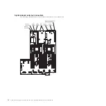
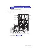
Front view
The following illustration shows the indicators on the front of the MAX5 expansion
module. All of the LEDs are controlled by the server integrated management
module (IMM).
Note:
The MAX5 expansion module does not have a power-on button. The MAX5
and all of its functions are controlled by the server to which it is connected.
Power-on
LED
Locator
button/LED
Power supply
error LED
Memory
LED
error
Link
LED
error
Fan
LED
error
System board
LED
error
Configuration
LED
error
v
Operator information panel:
This panel contains the indicators for the MAX5
expansion module.
–
Power-on LED:
When this green LED is lit, it indicates that the MAX5 is
powered on.
–
Locate LED:
Use this blue LED to locate the MAX5 expansion module. The
locate LED also has a button that you can press to light up other servers or
other MAX5 expansion modules to which the MAX5 is connected.
–
Power supply fault (error) LED:
When this amber LED is lit, it indicates a
faulty hot-swap power-supply.
–
Memory error LED:
When this amber LED is lit, it indicates a DIMM
problem.
–
Link error LED:
When this amber LED is lit, indicates that a QPI link fault or
a EXA link fault has occurred. The port LED for the link that has been
disconnected will not be lit on the rear of the MAX5. EXA link LEDs are on
the rear of the MAX5 expansion module and the QPI link LEDs are on the
server to which the MAX5 is connected.
–
Fan error LED:
When this amber LED is lit, it indicates a fan error.
–
System board error LED:
When this amber LED is lit, it indicates a MAX5
system-board tray error.
–
Configuration error LED:
When this amber LED is lit, it indicates a
configuration error. The memory error LED might be lit to indicate a memory
configuration error.
Chapter 2. Introduction
29
Содержание System x3690 X5
Страница 1: ...System x3690 X5 Types 7147 7148 7149 and 7192 Problem Determination and Service Guide...
Страница 2: ......
Страница 3: ...System x3690 X5 Types 7147 7148 7149 and 7192 Problem Determination and Service Guide...
Страница 8: ...vi System x3690 X5 Types 7147 7148 7149 and 7192 Problem Determination and Service Guide...
Страница 13: ...Safety statements Safety xi...
Страница 22: ...4 System x3690 X5 Types 7147 7148 7149 and 7192 Problem Determination and Service Guide...
Страница 266: ...248 System x3690 X5 Types 7147 7148 7149 and 7192 Problem Determination and Service Guide...
Страница 278: ...260 System x3690 X5 Types 7147 7148 7149 and 7192 Problem Determination and Service Guide...
Страница 386: ...368 System x3690 X5 Types 7147 7148 7149 and 7192 Problem Determination and Service Guide...
Страница 407: ...1 2 Chapter 5 Removing and replacing components 389...
Страница 444: ...426 System x3690 X5 Types 7147 7148 7149 and 7192 Problem Determination and Service Guide...
Страница 453: ...People s Republic of China Class A electronic emission statement Taiwan Class A compliance statement Notices 435...
Страница 454: ...436 System x3690 X5 Types 7147 7148 7149 and 7192 Problem Determination and Service Guide...
Страница 461: ...weight of memory enclosure 28 Index 443...
Страница 462: ...444 System x3690 X5 Types 7147 7148 7149 and 7192 Problem Determination and Service Guide...
Страница 463: ......
Страница 464: ...Part Number 47C8865 Printed in USA 1P P N 47C8865...