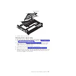
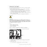


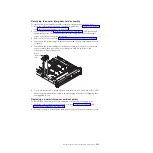


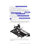


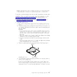


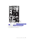

Retention latch
Drive backplane
4.
Reconnect the cables to the drive backplane and adapter, if it was removed.
5.
Reinstall the fan cage assembly (see “Replacing the fan cage assembly” on
page 332).
6.
Reinstall the drives and filler panels.
7.
Install the cover (see “Replacing the server top cover” on page 265).
8.
Slide the server into the rack.
9.
Reconnect the power cords and any cables that you removed.
10.
Turn on the peripheral devices and the server.
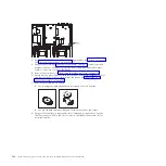
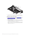
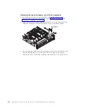
Removing the 8x1.8-inch hot-swap drive backplane assembly
To remove the 8x1.8-inch hot-swap drive backplane assembly, complete the
following steps:
1.
Read the safety information and installation guidelines, see “Safety” on page vii
and “Installation guidelines” on page 261.
2.
Turn off the server (see “Turning off the server” on page 17) and all attached
peripheral devices. Disconnect all power cords; then, disconnect all external
cables as necessary to replace the device.
3.
Remove the top cover (see “Removing the server top cover” on page 264).
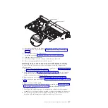
4.
Remove the fan cage assembly (see “Removing the fan cage assembly” on page
331).
5.
Remove the drive filler panel.
6.
Remove the drives from the drive backplane assembly (see “Removing 2.5-inch
and 1.8-inch hot-swap drives” on page 278) and install them in the new
backplane assembly.
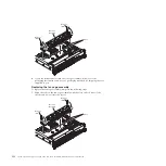
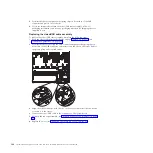
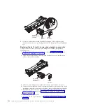
7.
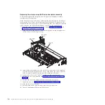
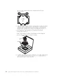
Disconnect the combination power/configuration cable from the backplane
assembly. If a SAS signal cable is attached to the drive backplane, disconnect it.
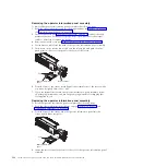
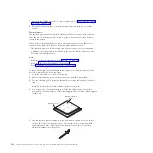
8.
Lift up the spring release latch slightly while pushing the assembly from the
back and slide the backplane assembly out the front of the server.
Chapter 5. Removing and replacing components
345
Содержание System x3690 X5
Страница 1: ...System x3690 X5 Types 7147 7148 7149 and 7192 Problem Determination and Service Guide...
Страница 2: ......
Страница 3: ...System x3690 X5 Types 7147 7148 7149 and 7192 Problem Determination and Service Guide...
Страница 8: ...vi System x3690 X5 Types 7147 7148 7149 and 7192 Problem Determination and Service Guide...
Страница 13: ...Safety statements Safety xi...
Страница 22: ...4 System x3690 X5 Types 7147 7148 7149 and 7192 Problem Determination and Service Guide...
Страница 266: ...248 System x3690 X5 Types 7147 7148 7149 and 7192 Problem Determination and Service Guide...
Страница 278: ...260 System x3690 X5 Types 7147 7148 7149 and 7192 Problem Determination and Service Guide...
Страница 386: ...368 System x3690 X5 Types 7147 7148 7149 and 7192 Problem Determination and Service Guide...
Страница 407: ...1 2 Chapter 5 Removing and replacing components 389...
Страница 444: ...426 System x3690 X5 Types 7147 7148 7149 and 7192 Problem Determination and Service Guide...
Страница 453: ...People s Republic of China Class A electronic emission statement Taiwan Class A compliance statement Notices 435...
Страница 454: ...436 System x3690 X5 Types 7147 7148 7149 and 7192 Problem Determination and Service Guide...
Страница 461: ...weight of memory enclosure 28 Index 443...
Страница 462: ...444 System x3690 X5 Types 7147 7148 7149 and 7192 Problem Determination and Service Guide...
Страница 463: ......
Страница 464: ...Part Number 47C8865 Printed in USA 1P P N 47C8865...