IBM System x3690 X5 Скачать руководство пользователя страница 289

Replacing the DIMM air baffle

To install the DIMM air baffle, complete the following steps:

1.

Read the safety information that begins on page “Safety” on page vii and
“Installation guidelines” on page 261.

2.

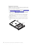
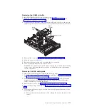
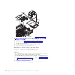
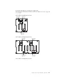
Align the tabs on the sides of the DIMM air baffle with the slots on the power
supply cage and the chassis wall and lower the DIMM air baffle into the server.

DIMM
air baffle

Alignment slots

RAID
battery
trays

3.

Reinstall the cover (see “Replacing the server top cover” on page 265).

4.

Slide the server into the rack.

5.

Reconnect the power cord and any cables that you removed.

6.

Turn on the peripheral devices and the server.

Attention:

For proper cooling and airflow, replace the air baffle before turning

on the server. Operating the server with an air baffle removed might damage
server components.

Removing the SAS cable guide

To remove the SAS cable guide, complete the following steps:

1.

Read the safety information and installation guidelines, see “Safety” on page vii
and “Installation guidelines” on page 261.

2.

Turn off the server (see “Turning off the server” on page 17) and all attached
peripheral devices. Disconnect all power cords; then, disconnect all external
cables as necessary to replace the device.

3.

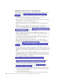
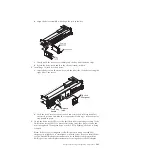
Remove the top cover (see “Removing the server top cover” on page 264).

4.

Remove the fan cage assembly (see “Removing the fan cage assembly” on page
331).

5.

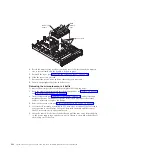
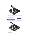
Disconnect and remove any SAS cables from the cable guide, then remove the
SAS cable guide.

a.

Remove the screw from the front of the cable guide (toward the front of the
server).

Chapter 5. Removing and replacing components

271

Содержание System x3690 X5

Страница 1: ...System x3690 X5 Types 7147 7148 7149 and 7192 Problem Determination and Service Guide...

Страница 2: ......

Страница 3: ...System x3690 X5 Types 7147 7148 7149 and 7192 Problem Determination and Service Guide...

Страница 4: ...nformation IBM Environmental Notices and User s Guide on the IBM Documentation CD and the IBM Warranty Information document that comes with the server Twelveth Edition February 2013 Copyright IBM Corp...

Страница 5: ...0 Hypervisor problems 51 General problems 52 Hard disk drive problems 52 Intermittent problems 54 Keyboard mouse or pointing device problems 55 Memory problems 57 Microprocessor problems 58 Monitor an...

Страница 6: ...ed hypervisor flash device 322 Replacing a USB embedded hypervisor flash device 324 Removing a hot swap power supply 324 Replacing a hot swap power supply 326 Removing a hot swap fan assembly 328 Repl...

Страница 7: ...Ethernet controller 414 Configuring RAID arrays 415 IBM Advanced Settings Utility program 415 Updating IBM Systems Director 416 Updating the Universal Unique Identifier UUID 417 Updating the DMI SMBI...

Страница 8: ...vi System x3690 X5 Types 7147 7148 7149 and 7192 Problem Determination and Service Guide...

Страница 9: ...rifterne f r du installerer dette produkt Lees voordat u dit product installeert eerst de veiligheidsvoorschriften Ennen kuin asennat t m n tuotteen lue turvaohjeet kohdasta Safety Information Avant d...

Страница 10: ...ar este producto lea la informaci n de seguridad L s s kerhetsinformationen innan du installerar den h r produkten Bu r n kurmadan nce g venlik bilgilerini okuyun Guidelines for trained service techni...

Страница 11: ...e or a bulging capacitor v Mechanical hazards such as loose or missing hardware To inspect the product for potential unsafe conditions complete the following steps 1 Make sure that the power is off an...

Страница 12: ...ies or remove or install main units v Before you work on the equipment disconnect the power cord If you cannot disconnect the power cord have the customer power off the wall box that supplies power to...

Страница 13: ...Safety statements Safety xi...

Страница 14: ...an electrical storm v Connect all power cords to a properly wired and grounded electrical outlet v Connect to properly wired outlets any equipment that will be attached to this product v When possibl...

Страница 15: ...nto water v Heat to more than 100 C 212 F v Repair or disassemble Dispose of the battery as required by local ordinances or regulations Statement 3 CAUTION When laser products such as CD ROMs DVD driv...

Страница 16: ...e Classe 1 Statement 4 18 kg 39 7 lb 32 kg 70 5 lb 55 kg 121 2 lb CAUTION Use safe practices when lifting Statement 5 CAUTION The power control button on the device and the power switch on the power s...

Страница 17: ...l attached There are no serviceable parts inside these components If you suspect a problem with one of these parts contact a service technician Statement 26 CAUTION Do not place any object on top of r...

Страница 18: ...chinenl rminformations Verordnung 3 GPSGV der h chste Schalldruckpegel betr gt 70 dB A oder weniger United Kingdom Notice to Customers This apparatus is approved under approval number NS G 1234 J 1000...

Страница 19: ...osis of hardware and software problems v Light path diagnostics LEDs See Light path diagnostics on page 67 for information about using light path diagnostics LEDs v Event logs See Event logs on page 3...

Страница 20: ...ystem updates 1 Determine the existing code levels In DSA click Firmware VPD to view system firmware levels or click Software to view operating system levels 2 Download and install updates of code tha...

Страница 21: ...ntifiable symptoms A single problem might cause multiple symptoms Follow the troubleshooting procedure for the most obvious symptom If that procedure does not diagnose the problem use the procedure fo...

Страница 22: ...4 System x3690 X5 Types 7147 7148 7149 and 7192 Problem Determination and Service Guide...

Страница 23: ...s v Consumable parts Purchase and replacement of consumable parts components such as batteries and printer cartridges that have depletable life is your responsibility If IBM acquires or installs a con...

Страница 24: ...ides translated versions of the IBM License Agreement for Machine Code for your product v Licenses and Attributions Document This document is in PDF format on the IBM Documentation CD It provides the...

Страница 25: ...t help you avoid inconvenient or problem situations v Attention These notices indicate potential damage to programs devices or data An attention notice is placed just before the instruction or situati...

Страница 26: ...MAX5 for System x memory expansion module another 1 TB of additional memory is available depending on the model 3 The server can support a total of 2 TBs of memory when both the optional memory tray...

Страница 27: ...on the front of the chassis Four on the rear of the chassis Two internal on the low profile riser card in which one connection is for the optional USB flash device with embedded hypervisor software v...

Страница 28: ...culate contamination Attention Airborne particulates and reactive gases acting alone or in combination with other environmental factors such as humidity or temperature might pose a risk to the server...

Страница 29: ...hard disk drives or solid state drive When these LEDs are lit it indicates that the drive has failed If an optional IBM ServeRAID controller is installed in the server when this LED is flashing slowl...

Страница 30: ...r information on logging on to the IMM Web interface v Ethernet activity LEDs When any of these LEDs is flashing or flickering they indicate that the server is transmitting to or receiving signals fro...

Страница 31: ...op of the operator information panel Note The system service label on the underside of the cover also provides information about the location of the light path diagnostics LEDs To access the light pat...

Страница 32: ...T A checkpoint code is either a byte or a word value that is produced by UEFI The display does not provide error codes or suggest components to be replaced v Reset button Press this button to reset th...

Страница 33: ...card supports v Power connector Connect the power cord to this connector v AC power LED Each hot swap power supply has an ac power LED and a dc power LED When the ac power LED is lit it indicates tha...

Страница 34: ...to this connector The serial port is shared with the integrated management module IMM The IMM can take control of the shared serial port to perform text console redirection and to redirect serial tra...

Страница 35: ...n power is restored v If your operating system supports the Wake on LAN feature the Wake on LAN feature can turn on the server Note When 4 GB or more of memory physical or logical is installed some me...

Страница 36: ...operating system supports this feature v If the operating system stops functioning you can press and hold the power control button for more than 4 seconds to turn off the server v The integrated manag...

Страница 37: ...System board internal connectors The following illustration shows the internal connectors on the system board Chapter 2 Introduction 19...

Страница 38: ...System board external connectors The following illustration shows the external connectors on the system board 20 System x3690 X5 Types 7147 7148 7149 and 7192 Problem Determination and Service Guide...

Страница 39: ...itch block you must remove and discard it to access the switch The following table describes the jumpers on the system board Table 2 System board jumpers Jumper number Jumper name Jumper setting J59 U...

Страница 40: ...ber Default position Description 1 Off Clear CMOS memory When this switch is toggled to On it clears the data in CMOS memory which clears the power on password 2 Off Reserved 3 Off Power on password o...

Страница 41: ...Turning off the server on page 17 2 Any system board switch or jumper blocks that are not shown in the illustrations in this document are reserved System board LEDs The following illustration shows t...

Страница 42: ...hows the connectors for user installable optional devices Optional 16 DIMM memory tray The following illustration shows the connectors and LEDs on the optional 16 DIMM memory tray 24 System x3690 X5 T...

Страница 43: ...on the optional three slot PCI riser card Side 1 PCI riser card Slot 3 PCI Express Gen2 low profile x8 Slot 4 PCI Express Gen2 low profile x8 x4 Side 2 USB connector USB embedded hypervisor flash dev...

Страница 44: ...ess Gen2 x8 PCI slot 1 error LED PCI slot 2 error LED Slot 2 PCI Express Gen2 x8 PCI riser card with one slot The following illustration shows the connector and LED on the optional one slot PCI riser...

Страница 45: ...at the IBM website at http www ibm com systems support The documentation provides additional installation and configuration information that you need to follow before you use the MAX5 DIMMs depending...

Страница 46: ...particulates and gases see Particulate contamination on page 429 Heat output Approximate heat output v Minimum configuration 314 Btu per hour 92 watts v Maximum configuration 2048 Btu per hour 600 wa...

Страница 47: ...Use this blue LED to locate the MAX5 expansion module The locate LED also has a button that you can press to light up other servers or other MAX5 expansion modules to which the MAX5 is connected Power...

Страница 48: ...iller panel in each of these connectors Attention When you handle the QPI cables take precautions to avoid damaging the high density interface Dropping and incorrectly connecting the QPI cables can da...

Страница 49: ...sues a power off request and you have disconnected the MAX5 power cord from the power source You cannot turn off the MAX5 expansion module manually Statement 5 CAUTION The power control button on the...

Страница 50: ...er slightly from your hardware Power supply 2 connector Power supply 1 connector Supercap capacitor Turn on LEDs button Information panel connector 5 drop fan cable connector DIMM connectors 17 24 DIM...

Страница 51: ...shooting tables on page 50 for more information v IBM Dynamic System Analysis Two editions of IBM Dynamic System Analysis DSA are available for diagnosing problems DSA Portable and DSA Preboot DSA Por...

Страница 52: ...and configuration System configuration Vital product data firmware and UEFI configuration DSA Preboot also provides diagnostics for the following system components when they are installed 1 Broadcom n...

Страница 53: ...ntegrated management module IMM You can view the contents of the system event log through the Setup utility and through the Dynamic System Analysis DSA program as IPMI event log The system event log i...

Страница 54: ...event log or the IMM event log as the ASM event log the operating system event logs or the merged DSA log You can also use DSA Preboot to view these logs although you must restart the server to use D...

Страница 55: ...log locally requires RNDIS USB LAN driver For more information see Obtaining the IP address for the IMM on page 413 and Logging on to the Web interface on page 413 The integrated management module IMM...

Страница 56: ...a series of tests to check the operation of the server components and some optional devices in the server This series of tests is called the power on self test or POST Note This server does not use be...

Страница 57: ...art the server If the error is corrected then microprocessor 1 is bad and must be replaced 4 Replace the following components one at a time in the order shown restarting the server each time a Trained...

Страница 58: ...is installed correctly see Replacing a memory module on page 296 for more information 2 If the DIMM was disabled because of a memory error following the suggested actions for that error event and rest...

Страница 59: ...this memory error 2 At the next maintenance opportunity swap the affected DIMM as indicated by the light path LED or event log entry to a different memory channel See Replacing a memory module on page...

Страница 60: ...00580A1 Invalid DIMM population for mirroring mode 1 If a fault LED is lit resolve the failure 2 Install the DIMMs in the correct sequence see Replacing a memory module on page 296 00580A4 Memory pop...

Страница 61: ...PCI adapter firmware 4 Remove the adapter from the riser card 5 Replace the following components one at a time in the order shown restarting the server each time a Adapter b Trained service technicia...

Страница 62: ...alues see Table 3 on page 22 3 Remove any recently installed hardware 3038003 Firmware corrupted 1 Switch to the backup firmware bank then updated to the latest level of firmware 2 Run the Setup utili...

Страница 63: ...en it must be replaced by a trained service technician only c Trained service technician only System board 3058004 Three boot failure 1 Undo any recent system changes such as new settings or newly ins...

Страница 64: ...ce or IPMItool to clear the logs from the operating system v When using the local console 1 Run the Setup utility see Using the Setup utility on page 402 2 Select System Event Log 3 Select Clear Syste...

Страница 65: ...y Replace the system board 3818007 CRTM update capsule signature invalid 1 Run the Setup utility select Load Default Settings and save the settings 2 Trained service technician only Replace the system...

Страница 66: ...failing server is part of a shared hard disk drive cluster two or more servers sharing external storage devices If it is part of a cluster you can run all diagnostic programs except the ones that tes...

Страница 67: ...page 67 Note When you slide the light path diagnostics panel out of the server to check the LEDs or checkpoint codes do not run the server continuously with light path diagnostics panel outside of the...

Страница 68: ...on page 82 4 Reinstall the new software or new device CD DVD drive problems v Follow the suggested actions in the order in which they are listed in the Action column until the problem is solved v See...

Страница 69: ...VD drive on page 291 4 Replace the CD or DVD drive Hypervisor problems v Follow the suggested actions in the order in which they are listed in the Action column until the problem is solved v See Chapt...

Страница 70: ...90 X5 Types 7147 7148 7149 and 7192 on page 249 to determine which components are customer replaceable units CRU and which components are field replaceable units FRU v If an action step is preceded by...

Страница 71: ...ns the same go to step 4 If the activity of the LEDs changes return to step 1 4 Make sure that the hard disk drive backplane is correctly seated When it is correctly seated the drive assemblies correc...

Страница 72: ...te of the associated drive 1 If the amber hard disk drive LED and the RAID adapter software do not indicate the same status for the drive complete the following steps a Turn off the server b Reseat th...

Страница 73: ...river If the reset continues to occur after the operating system starts the operating system might have a problem see Software problems on page 66 3 If neither condition applies check the event logs s...

Страница 74: ...e compatibility 2 Make sure that v The mouse or pointing device cable is securely connected to the server v If you are using a pointing device the keyboard and mouse or pointing device cables are not...

Страница 75: ...a systems management interrupt SMI replace the DIMM v If a DIMM was disabled by the user or by POST run the Setup utility and enable the DIMM 3 Run memory diagnostics see IBM Dynamic System Analysis...

Страница 76: ...the order shown restarting the server each time a Trained service technician only Microprocessor b Trained service technician only System board Monitor and video problems Some IBM monitors have their...

Страница 77: ...ly 3 Make sure that the correct server is controlling the monitor if applicable 4 Make sure that damaged server firmware is not affecting the video see Updating the firmware on page 397 5 Observe the...

Страница 78: ...r while it is turned on might cause screen discoloration Move the device and the monitor at least 305 mm 12 in apart and turn on the monitor Notes a To prevent diskette drive read write errors make su...

Страница 79: ...he device is installed correctly v You have not loosened any other installed devices or cables v You updated the configuration information in the Setup utility Whenever memory or any other device is c...

Страница 80: ...es not start bypass the power control button by using the force power on jumper see Server internal LEDs connectors and jumpers on page 18 If the server starts reseat the operator information panel If...

Страница 81: ...n the following order a Remove the all hard disk drives or solid state drives and drive backplanes Try restarting the server If the server starts reinstall the hard disk drives or solid state drives a...

Страница 82: ...e server If the server starts reinstall the memory tray Restart the server if the problem remains 2 Replace any failing device 3 Trained service technician only Replace the system board If the Channel...

Страница 83: ...s listed in step 2 one at a time in the order shown restarting the server each time 4 Trained service technician only Replace the system board ServerGuide problems v Follow the suggested actions in th...

Страница 84: ...e Make sure that the server supports the operating system If it does either no logical drive is defined SCSI RAID servers or the ServerGuide System Partition is not present Run the ServerGuide program...

Страница 85: ...nostics Light path diagnostics is a system of LEDs on various external and internal components of the server When an error occurs LEDs are lit throughout the server By viewing the LEDs in a particular...

Страница 86: ...ensure proper cooling The following illustration shows the light path diagnostics panel Note any LEDs that are lit and then reinstall the light path diagnostics panel in the server v Remind button Pre...

Страница 87: ...ss the button The Reset button is in the lower right corner of the light path diagnostics panel Look at the system service label inside the server cover which gives an overview of internal components...

Страница 88: ...using more power than their maximum rating If the OVER SPEC LED is lit use one of the following procedures 1 Turn off the server disconnect the power from the server and install additional power suppl...

Страница 89: ...cessor error has been detected 1 Remove power from the server then reconnect the server to power and restart the server 2 Update the IMM firmware see Updating the firmware on page 397 3 Trained servic...

Страница 90: ...rted see Replacing a memory module on page 296 for DIMM requirements and installation sequence information b Replace the DIMMs with a supported configuration CPU An invalid microprocessor configuratio...

Страница 91: ...after each a Replace the hard disk drive b Replace the hard disk drive backplane 5 If the error remains replace the following components one at a time in the order listed restarting the server after e...

Страница 92: ...omplete the following steps 1 Turn off the server and disconnect the power from the server 2 Remove the optical drive and fans one at a time 3 Restart the server to see whether the problem remains 4 R...

Страница 93: ...er from the server 2 Remove all installed PCI Express adapters 3 Restart the server to see whether the problem remains 4 Reinstall each device that you removed in step 2 one at a time starting the ser...

Страница 94: ...moved in step 2 one at a time starting the server each time to isolate the failing device 6 Replace any failing device 7 Trained service technician only Replace the system board If the 12 V channel F...

Страница 95: ...e server cover 3 Restart the server Over current error LED An electrical over current error has occurred which caused the power supplies to shutdown If the Over current error LED is lit see System boa...

Страница 96: ...on the operator information panel and suggested actions to correct the detected problems Power supply LEDs Description Action Notes AC DC Error On On Off Normal operation Off Off Off No ac power to t...

Страница 97: ...is closed and latched correctly 2 Reseat the power supply 3 If the 240 V failure LED on the system board is not lit replace the power supply 4 If the 240 V failure LED on the system board is lit trai...

Страница 98: ...nique DSA interfaces 2 DSA Preboot might appear to be unresponsive when you start the program This is normal operation while the program loads Make sure that the server has the latest version of the D...

Страница 99: ...e DSA Preboot diagnostic programs For more information and to download the utilities go to http www 947 ibm com systems support supportsite wss docdisplay brandind 5000008 lndocid SERV DSA Running the...

Страница 100: ...the Execute Tests menu if you are running the DSA interactive menu or select Diagnostic Event Log in the graphical user interface To transfer DSA Preboot collections to an external USB device type the...

Страница 101: ...program error 1 Turn off and restart the system 2 Make sure that the DSA code is at the latest level For the latest level of DSA code go to http www ibm com support docview wss uid psg1SERV DSA 3 Run...

Страница 102: ...or the latest level of DSA code go to http www ibm com support docview wss uid psg1SERV DSA 3 Run the test again 4 Make sure that the system firmware is at the latest level The installed firmware leve...

Страница 103: ...t At least 1 GB required 1 Turn off and restart the system if necessary to recover from a hung state 2 Make sure that the DSA code is at the latest level For the latest level of DSA code go to http ww...

Страница 104: ...cessary to recover from a hung state 2 Make sure that the DSA code is at the latest level For the latest level of DSA code go to http www ibm com support docview wss uid psg1SERV DSA 3 Run the test ag...

Страница 105: ...1 xxx IMM IMM I2 C Test Aborted IMM I2C test stopped the IMM returned an incorrect response length 1 Turn off the system and disconnect it from the power source You must disconnect the system from ac...

Страница 106: ...I2C test stopped the test cannot be completed for an unknown reason 1 Turn off the system and disconnect it from the power source You must disconnect the system from ac power to reset the IMM 2 After...

Страница 107: ...on 166 803 xxx IMM IMM I2 C Test Aborted IMM I2C test stopped the node is busy try later 1 Turn off the system and disconnect it from the power source You must disconnect the system from ac power to r...

Страница 108: ...C Test Aborted IMM I2C test stopped invalid command 1 Turn off the system and disconnect it from the power source You must disconnect the system from ac power to reset the IMM 2 After 45 seconds recon...

Страница 109: ...166 805 xxx IMM IMM I2 C Test Aborted IMM I2C test stopped invalid command for the given LUN 1 Turn off the system and disconnect it from the power source You must disconnect the system from ac power...

Страница 110: ...ted IMM I2C test stopped timeout while processing the command 1 Turn off the system and disconnect it from the power source You must disconnect the system from ac power to reset the IMM 2 After 45 sec...

Страница 111: ...on Action 166 807 xxx IMM IMM I2 C Test Aborted IMM I2C test stopped out of space 1 Turn off the system and disconnect it from the power source You must disconnect the system from ac power to reset th...

Страница 112: ...MM I2C test stopped reservation canceled or invalid reservation ID 1 Turn off the system and disconnect it from the power source You must disconnect the system from ac power to reset the IMM 2 After 4...

Страница 113: ...on 166 809 xxx IMM IMM I2 C Test Aborted IMM I2C test stopped request data was truncated 1 Turn off the system and disconnect it from the power source You must disconnect the system from ac power to r...

Страница 114: ...borted IMM I2C test stopped request data length is invalid 1 Turn off the system and disconnect it from the power source You must disconnect the system from ac power to reset the IMM 2 After 45 second...

Страница 115: ...11 xxx IMM IMM I2 C Test Aborted IMM I2C test stopped request data field length limit is exceeded 1 Turn off the system and disconnect it from the power source You must disconnect the system from ac p...

Страница 116: ...Aborted IMM I2C Test stopped a parameter is out of range 1 Turn off the system and disconnect it from the power source You must disconnect the system from ac power to reset the IMM 2 After 45 seconds...

Страница 117: ...xxx IMM IMM I2 C Test Aborted IMM I2C test stopped cannot return the number of requested data bytes 1 Turn off the system and disconnect it from the power source You must disconnect the system from ac...

Страница 118: ...MM I2C test stopped requested sensor data or record is not present 1 Turn off the system and disconnect it from the power source You must disconnect the system from ac power to reset the IMM 2 After 4...

Страница 119: ...66 815 xxx IMM IMM I2 C Test Aborted IMM I2C test stopped invalid data field in the request 1 Turn off the system and disconnect it from the power source You must disconnect the system from ac power t...

Страница 120: ...est stopped the command is illegal for the specified sensor or record type 1 Turn off the system and disconnect it from the power source You must disconnect the system from ac power to reset the IMM 2...

Страница 121: ...817 xxx IMM IMM I2 C Test Aborted IMM I2C test stopped a command response could not be provided 1 Turn off the system and disconnect it from the power source You must disconnect the system from ac pow...

Страница 122: ...ted IMM I2C test stopped cannot execute a duplicated request 1 Turn off the system and disconnect it from the power source You must disconnect the system from ac power to reset the IMM 2 After 45 seco...

Страница 123: ...C Test Aborted IMM I2C test stopped a command response could not be provided the SDR repository is in update mode 1 Turn off the system and disconnect it from the power source You must disconnect the...

Страница 124: ...M I2 C Test Aborted IMM I2C test stopped a command response could not be provided the device is in firmware update mode 1 Turn off the system and disconnect it from the power source You must disconnec...

Страница 125: ...2 C Test Aborted IMM I2C test stopped a command response could not be provided IMM initialization is in progress 1 Turn off the system and disconnect it from the power source You must disconnect the s...

Страница 126: ...borted IMM I2C test stopped the destination is unavailable 1 Turn off the system and disconnect it from the power source You must disconnect the system from ac power to reset the IMM 2 After 45 second...

Страница 127: ...IMM IMM I2 C Test Aborted IMM I2C test stopped cannot execute the command insufficient privilege level 1 Turn off the system and disconnect it from the power source You must disconnect the system from...

Страница 128: ...Aborted IMM I2C test stopped cannot execute the command 1 Turn off the system and disconnect it from the power source You must disconnect the system from ac power to reset the IMM 2 After 45 seconds...

Страница 129: ...s 0 1 Turn off the system and disconnect it from the power source You must disconnect the system from ac power to reset the IMM 2 After 45 seconds reconnect the system to the power source and turn on...

Страница 130: ...stem 3 Run the test again 4 Make sure that the DSA code is at the latest level For the latest level of DSA code go to http www ibm com support docview wss uid psg1SERV DSA 5 Make sure that the IMM fir...

Страница 131: ...You must disconnect the system from ac power to reset the IMM 2 After 45 seconds reconnect the system to the power source and turn on the system 3 Run the test again 4 Make sure that the DSA code is a...

Страница 132: ...hnician v Go to the IBM support Web site at http www ibm com supportportal to check for technical information hints tips and new device drivers or to submit a request for information Message number Co...

Страница 133: ...it from the power source You must disconnect the system from ac power to reset the IMM 2 After 45 seconds reconnect the system to the power source and turn on the system 3 Run the test again 4 Make s...

Страница 134: ...o reset the IMM 2 After 45 seconds reconnect the system to the power source and turn on the system 3 Run the test again 4 Make sure that the DSA code is at the latest level For the latest level of DSA...

Страница 135: ...ff the system and disconnect it from the power source You must disconnect the system from ac power to reset the IMM 2 After 45 seconds reconnect the system to the power source and turn on the system 3...

Страница 136: ...disconnect the server from ac power to reset the IMM 2 After 45 seconds reconnect the server to the power source and turn on the server 3 Run the test again 4 Make sure that the DSA code is at the lat...

Страница 137: ...ian v Go to the IBM support Web site at http www ibm com supportportal to check for technical information hints tips and new device drivers or to submit a request for information Message number Compon...

Страница 138: ...45 seconds reconnect the server to the power source and turn on the server 3 Run the test again 4 Make sure that the DSA code is at the latest level For the latest level of DSA code go to http www ibm...

Страница 139: ...wer source and turn on the server 3 Run the test again 4 Make sure that the DSA code is at the latest level For the latest level of DSA code go to http www ibm com support docview wss uid psg1SERV DSA...

Страница 140: ...n the test again 4 Make sure that the DSA code is at the latest level For the latest level of DSA code go to http www ibm com support docview wss uid psg1SERV DSA 5 Make sure that the IMM firmware is...

Страница 141: ...r source and turn on the server 3 Run the test again 4 Make sure that the DSA code is at the latest level For the latest level of DSA code go to http www ibm com support docview wss uid psg1SERV DSA 5...

Страница 142: ...re is at the latest level The installed firmware level is shown in the DSA event log in the Firmware VPD section for this component For more information see Updating the firmware on page 397 4 Run the...

Страница 143: ...e test again 3 Make sure that the server firmware is at the latest level The installed firmware level is shown in the DSA event log in the Firmware VPD section for this component For more information...

Страница 144: ...that the server firmware is at the latest level The installed firmware level is shown in the DSA event log in the Firmware VPD section for this component For more information see Updating the firmwar...

Страница 145: ...the test again 3 Make sure that the server firmware is at the latest level The installed firmware level is shown in the DSA event log in the Firmware VPD section for this component For more informatio...

Страница 146: ...server firmware is at the latest level The installed firmware level is shown in the DSA event log in the Firmware VPD section for this component For more information see Updating the firmware on page...

Страница 147: ...e sure that the server firmware is at the latest level The installed firmware level is shown in the DSA event log in the Firmware VPD section for this component For more information see Updating the f...

Страница 148: ...e that the server firmware is at the latest level The installed firmware level is shown in the DSA event log in the Firmware VPD section for this component For more information see Updating the firmwa...

Страница 149: ...uid psg1SERV DSA 4 Make sure that the server firmware is at the latest level The installed firmware level is shown in the DSA event log in the Firmware VPD section for this component For more informat...

Страница 150: ...4 Make sure that the server firmware is at the latest level The installed firmware level is shown in the DSA event log in the Firmware VPD section for this component For more information see Updating...

Страница 151: ...m support docview wss uid psg1SERV DSA 4 Make sure that the server firmware is at the latest level The installed firmware level is shown in the DSA event log in the Firmware VPD section for this compo...

Страница 152: ...nt Test State Description Action 201 824 xxx Memory Memory Test Aborted Test Aborted Node interleave must be OFF 1 Turn off and restart the system 2 Press F1 to go into the Setup utility and turn off...

Страница 153: ...essage number Component Test State Description Action 201 826 xxx Memory Memory Test Aborted Test Aborted Memory controller is disabled 1 Turn off and restart the system 2 Press F1 to go into the Setu...

Страница 154: ...est State Description Action 201 827 xxx Memory Memory Test Aborted Test Aborted ECC feature is disabled 1 Turn off and restart the system 2 Press F1 to go into the Setup utility and make sure that EC...

Страница 155: ...s uid psg1SERV DSA 4 Make sure that the server firmware is at the latest level The installed firmware level is shown in the DSA event log in the Firmware VPD section for this component For more inform...

Страница 156: ...at the server firmware is at the latest level The installed firmware level is shown in the DSA event log in the Firmware VPD section for this component For more information see Updating the firmware o...

Страница 157: ...psg1SERV DSA 4 Make sure that the server firmware is at the latest level The installed firmware level is shown in the DSA event log in the Firmware VPD section for this component For more information...

Страница 158: ...t the server firmware is at the latest level The installed firmware level is shown in the DSA event log in the Firmware VPD section for this component For more information see Updating the firmware on...

Страница 159: ...SERV DSA 4 Make sure that the server firmware is at the latest level The installed firmware level is shown in the DSA event log in the Firmware VPD section for this component For more information see...

Страница 160: ...ake sure that the server firmware is at the latest level The installed firmware level is shown in the DSA event log in the Firmware VPD section for this component For more information see Updating the...

Страница 161: ...id psg1SERV DSA 4 Make sure that the server firmware is at the latest level The installed firmware level is shown in the DSA event log in the Firmware VPD section for this component For more informati...

Страница 162: ...the server firmware is at the latest level The installed firmware level is shown in the DSA event log in the Firmware VPD section for this component For more information see Updating the firmware on p...

Страница 163: ...SA 4 Make sure that the server firmware is at the latest level The installed firmware level is shown in the DSA event log in the Firmware VPD section for this component For more information see Updati...

Страница 164: ...server firmware is at the latest level The installed firmware level is shown in the DSA event log in the Firmware VPD section for this component For more information see Updating the firmware on page...

Страница 165: ...cview wss uid psg1SERV DSA 4 Make sure that the server firmware is at the latest level The installed firmware level is shown in the DSA event log in the Firmware VPD section for this component For mor...

Страница 166: ...ate Description Action 201 894 xxx Memory Memory Test Unexpected error code 1 Turn off and restart the system 2 Run the test again 3 Make sure that the DSA code is at the latest level For the latest l...

Страница 167: ...Failed Test failure single bit error failing DIMM z 1 Turn off the system and disconnect it from the power source 2 Reseat DIMM z 3 Reconnect the system to power and turn on the system 4 Make sure tha...

Страница 168: ...e bit and multi bit error failing DIMM z 1 Turn off the system and disconnect it from the power source 2 Reseat DIMM z 3 Reconnect the system to power and turn on the system 4 Make sure that the DSA c...

Страница 169: ...ent Test State Description Action 202 801 xxx Memory Memory Stress Test Aborted Internal program error 1 Turn off and restart the system 2 Make sure that the DSA code is at the latest level For the la...

Страница 170: ...sary enable all memory in the Setup utility see Using the Setup utility on page 402 2 Make sure that the DSA code is at the latest level For the latest level of DSA code go to http www ibm com support...

Страница 171: ...ctions apply to all three tests Aborted Unable to communicate with the device driver 1 Make sure that the DSA code is at the latest level For the latest level of DSA code go to http www ibm com suppor...

Страница 172: ...in 5 Check the drive cabling at both ends for loose or broken connections or damage to the cable Replace the cable if it is damaged 6 Run the test again 7 Make sure that the DSA code is at the latest...

Страница 173: ...ds for loose or broken connections or damage to the cable Replace the cable if it is damaged 4 Run the test again 5 For additional troubleshooting information go to http www ibm com support docview ws...

Страница 174: ...talled v Read Write Test v Self Test Messages and actions apply to all three tests Aborted Could not access the drive 1 Insert a CD DVD into the drive or try a new media and wait for 15 seconds 2 Run...

Страница 175: ...Insert a CD DVD into the drive or try a new media and wait for 15 seconds 2 Run the test again 3 Check the drive cabling at both ends for loose or broken connections or damage to the cable Replace the...

Страница 176: ...4 Make sure that the firmware is at the latest level 5 Run the test again 6 If the failure remains go to the IBM Web site for more troubleshooting information at http www ibm com systems support suppo...

Страница 177: ...97 2 Run the test again 3 Replace the component that is causing the error If the error is caused by an adapter replace the adapter Check the PCI Information and Network Settings information in the DSA...

Страница 178: ...the component firmware is at the latest level The installed firmware level is shown in the DSA event log in the Firmware VPD section for this component For more information see Updating the firmware...

Страница 179: ...rrupt Failed 1 Make sure that the component firmware is at the latest level The installed firmware level is shown in the DSA event log in the Firmware VPD section for this component For more informati...

Страница 180: ...Broadcom Ethernet Device Test Loop back at MAC Layer Failed 1 Check the Ethernet cable for damage and make sure that the cable type and connection are correct 2 Make sure that the component firmware...

Страница 181: ...more information see Updating the firmware on page 397 3 Run the test again 4 Replace the component that is causing the error If the error is caused by an adapter replace the adapter Check the PCI In...

Страница 182: ...cause the server to malfunction Before you install a firmware or device driver update read any readme and change history files that are provided with the downloaded update These files contain importa...

Страница 183: ...llowing the instructions that are in the firmware update package readme file 9 Copy the downloaded firmware update package into a directory 10 From a command line type filename s where filename is the...

Страница 184: ...I update failure or UEFI image corruption on page 164 After you have recovered the firmware in the primary bank complete the following steps 1 Restart the server 2 When the prompt press F3 to restore...

Страница 185: ...e instance this can result in two different messages being logged for the same event For example if fan 4 in the MAX5 is removed the following two event messages will be logged for the same fan event...

Страница 186: ...stem x3690 X5 IMM error messages v Follow the suggested actions in the order in which they are listed in the Action column until the problem is solved v See Chapter 4 Parts listing System x3690 X5 Typ...

Страница 187: ...has asserted Info Sensor has reported power usage increase from normal to non critical state Information only no action is required 80010703 1502xxxx Numeric sensor FG 2PS going high upper non critic...

Страница 188: ...r has detected a sensor transitioned to critical from less severe on the power supply 1 2 Make sure that the power supply is installed correctly see Replacing a hot swap power supply on page 326 Make...

Страница 189: ...Replacing a hot swap power supply on page 326 Make sure that no error LEDs are lit on the power supply and that all power supplies have the green LEDs lit 80010b01 0c01xxxx Numeric sensor Ambient Tem...

Страница 190: ...Numeric sensor FG 3PS going high upper non recoverable has asserted Error Power supply fuel gage error 1 The management controller has detected a sensor transitioned to critical from less severe on t...

Страница 191: ...e to 1 GB 2 Enable PCI 64 bit Resource a Run the Setup utility see Using the Setup utility on page 402 and select Devices and I O Ports PCI 64 bit Resource b Enable PCI 64 bit Resource 80070114 2201xx...

Страница 192: ...echnician only Replace the system board 8007020c 2581xxxx Sensor MemSpareErrN has transitioned to critical from a less severe state N memory DIMM number Error A fatal communication error has occurred...

Страница 193: ...rom a less severe state n power supply number Error A sensor has changed to Critical state from a less severe state 1 Make sure that there are no obstructions such as bundled cables to the airflow fro...

Страница 194: ...ster solutions require specific code levels or coordinated code updates If the device is part of a cluster solution verify that the latest level of code is supported for the cluster solution before yo...

Страница 195: ...e the failing microprocessor see Removing a microprocessor and heat sink on page 349 and Replacing a microprocessor and heat sink on page 351 4 Check for a UEFI FPGA and IMM firmware update see Updati...

Страница 196: ...airflow front and rear of the server that the air baffles are in place and correctly installed and that the server cover is installed and completely closed 2 Make sure that the heat sink for micropro...

Страница 197: ...sed 2 Check the ambient temperature You must be operating within the specifications 3 Make sure that the heat sink for microprocessor n is installed correctly 4 Trained service technician only Replace...

Страница 198: ...oard 80070608 1406xxxx Sensor 5V Power Good has transitioned to non recoverable Error Trained service technician only Replace the system board 80070608 0a01xxxx 80070608 0a02xxxx 80070608 0a03xxxx 800...

Страница 199: ...al No action informational only Sensor PS n has transitioned to a critical from a less severe state n power supply number Error An error has been detected for Power supply n 1 Check the power supply L...

Страница 200: ...ecoverable state 1 Turn off the server and disconnect it from power 2 Remove the optical drive fans hard disk drives and hard disk drive backplane 3 Reinstall each device one at a time starting the se...

Страница 201: ...coverable state 1 Turn off the server and disconnect it from power 2 Remove the SAS SATA RAID riser card the DIMMs in connectors 1 through 8 and the Trained service technician only microprocessor in s...

Страница 202: ...2 3 Reinstall each device one at a time starting the server each time to isolate the failing device 4 Replace the failing device 5 Trained service technician only Replace the system board Sensor Pwr...

Страница 203: ...r status LEDs to identify the failed hard disk drive or check the RAID controller system management software event logs 2 Reseat the hard disk drive for which the status LED is lit 3 Replace the defec...

Страница 204: ...nsufficient Resources for RedundancySetElementName has asserted Error Cooling zone alert Cooling zone 5 error Replace fan 5 806f0007 0301xxxx 806f0007 0302xxxx The Processor CPU n Status has Failed wi...

Страница 205: ...ty Description Action 806f0021 2582xxxx Fault in slot System board on system 1 1 CIM_ComputerSystem ElementName All PCI Error One of PCI Error 1 Check the riser card LEDs 2 Reseat the affected adapter...

Страница 206: ...021 2201xxxx Fault in slot System board on system 1 1 CIM_ComputerSystem ElementName No Op ROM Space Error 1 Check the riser card LEDs 2 Reseat the affected adapters and riser card 3 Update the server...

Страница 207: ...er card 3 Update the server firmware UEFI and IMM and adapter firmware Important Some cluster solutions require specific code levels or coordinated code updates If the device is part of a cluster solu...

Страница 208: ...ard disk drive number Error A drive has been disabled because of a fault 1 Run the hard disk drive diagnostic test on drive n 2 Reseat the following components a Hard disk drive wait 1 minute or more...

Страница 209: ...ocessor failed FRB1 BIST condition has occurred 1 Check for a server firmware update Important Some cluster solutions require specific code levels or coordinated code updates If the device is part of...

Страница 210: ...update read any readme and change history files that are provided with the downloaded update These files contain important information about the update and the procedure for installing the update inc...

Страница 211: ...s require specific code levels or coordinated code updates If the device is part of a cluster solution verify that the latest level of code is supported for the cluster solution before you update the...

Страница 212: ...and IMM see Updating the firmware on page 397 806f052b 2101xxxx Invalid or Unsupported firmware or software was detected on System n n system serial number Error An IMM firmware failover has occurred...

Страница 213: ...e 2 Update the server firmware to the latest level see Updating the firmware on page 397 Important Some cluster solutions require specific code levels or coordinated code updates If the device is part...

Страница 214: ...Important Some cluster solutions require specific code levels or coordinated code updates If the device is part of a cluster solution verify that the latest level of code is supported for the cluster...

Страница 215: ...k for a server firmware update Important Some cluster solutions require specific code levels or coordinated code updates If the device is part of a cluster solution verify that the latest level of cod...

Страница 216: ...ime restarting the server each time c If the error recurs replace the component that you just reinstalled 2 Reseat power supply n 3 Replace power supply n n power supply number 806f0109 1381xxxx Host...

Страница 217: ...a DIMM of the same size and type from a different memory channel 3 Run the Setup utility to enable all the DIMMs 4 If the DIMM still fails on a different memory channel replace the DIMM 5 If the swap...

Страница 218: ...t panel 806f0125 1801xxxx ManagedElementName detected as absent Info The management controller has detected a Managed Element is absent 1 Make sure that the memory tray is properly seated and connecte...

Страница 219: ...management controller has detected a Managed Element is Absent 1 Make sure that the memory expansion module fan cable is properly seated and connected 2 Replace the memory expansion module fan cable...

Страница 220: ...rom a different memory channel 3 Run the Setup utility to enable all the DIMMs 4 If the DIMM still fails on a different memory channel replace the DIMM 5 If the swapped DIMM fails on the original DIMM...

Страница 221: ...IMMs on subsystem System Memory Error A Memory Scrub failure has been detected 1 Check IBM support site for an applicable RETAIN tip or firmware update that applies to this memory error 2 Swap the aff...

Страница 222: ...tart the server 3 Check the IBM support site for an applicable RETAIN tip or firmware update that applies to this memory error 4 If no memory error is recorded in the event logs and no DIMM connector...

Страница 223: ...for more information 2 If the DIMM was disabled because of a memory error follow the suggested actions for that error event and restart the server 3 Check the IBM support site for an applicable RETAI...

Страница 224: ...stem System Memory Error The memory logging limit has been reached 1 Check IBM support site for an applicable RETAIN tip or firmware update that applies to this memory error 2 At the next maintenance...

Страница 225: ...ed for DIMM All DIMMs on Memory Subsystem All DIMMs Error The memory logging limit has been reached 1 Check IBM support site for an applicable RETAIN tip or firmware update that applies to this memory...

Страница 226: ...memory module on page 296 for information on DIMM population sequence 3 If the PFA re occurs on the same DIMM replace the affected DIMM as indicated by the light path LED or event log entry check for...

Страница 227: ...has occurred 1 If the server failed the POST memory test reseat the DIMMs 2 Replace any DIMM that is indicated by a lit error LED Note You do not have to replace DIMMs by pairs 3 Run the Setup utilit...

Страница 228: ...ailed complete the action for a fan failure 4 Replace DIMM n n DIMM number 806f0823 2101xxxx Watchdog Timer interrupt occurred for Watchdog Info The IPMI Watchdog Timer has expired A watchdog interrup...

Страница 229: ...place and correctly installed 4 Make sure that the room temperature is within operating specifications 806f0a0c 2587xxxx An Over Temperature Condition has been detected on the PhysicalMemoryElementNam...

Страница 230: ...V has deasserted the transition to non recoverable Error A VRD error is detected Trained service technician only Replace the system board 81070608 0a01xxxx 81070608 0a02xxxx 81070608 0a03xxxx 81070608...

Страница 231: ...xx 816f000d 0412xxxx 816f000d 0413xxxx 816f000d 0414xxxx 816f000d 0415xxxx 816f000d 0416xxxx 816f000d 0417xxxx 816f000d 0418xxxx 816f000d 0419xxxx 816f000d 041axxxx 816f000d 041bxxxx 816f000d 041cxxxx...

Страница 232: ...Port Speed 3 user ID Info A user has modified the Ethernet port data rate No action information only Ethernet Duplex setting modified from 1 to 2 by user 3 1 CIM_EthernetPort FullDuplex 2 CIM_Ethernet...

Страница 233: ...ke sure that the network cable is connected 2 Make sure that there is a DHCP server on the network that can assign an IP address to the IMM Remote Login Successful Login ID 1 from 2 at IP address 3 1...

Страница 234: ...istrator reset the login ID or password 40000026 00000000 The Chassis Event Log CEL on system 1 cleared by user 2 1 CIM_ComputerSystem ElementName 2 user ID Info A user has cleared the IMM event log N...

Страница 235: ...1 restored from a configuration file by user 2 1 CIM_ConfigurationData ConfigurationName 2 user ID Info A user has restored the IMM configuration by importing a configuration file No action informati...

Страница 236: ...talled operating system 6 Update the IMM firmware Important Some cluster solutions require specific code levels or coordinated code updates If the device is part of a cluster solution verify that the...

Страница 237: ...set to the date and time that is provided by the Network Time Protocol server No action information only 40000022 00000000 SSL data in the IMM configuration data is invalid Clearing configuration data...

Страница 238: ...the log is full older log entries are replaced by newer ones To avoid losing older log entries save the log as a text file and clear the log 40000027 00000000 1 Platform Watchdog Timer expired for 2...

Страница 239: ...dancy degraded or fully redundant to non redundant sufficient MAX5 power supplies are non redundant 800b050a 1e86xxxx Non redundant Insufficient Resources for RedundancySetElementName has asserted Err...

Страница 240: ...as absent Info The MAX5 memory expansion module is not working properly Check the MAX5 memory expansion module cables and power connections A hardware change occurred on system Host Info Changes were...

Страница 241: ...place the failing fan n fan number 80010701 1881xxxx Numeric sensor MEU Chipset Temp going high upper non critical has asserted Info Sensor has reported temperature increase from normal to non critica...

Страница 242: ...iloverMEU has asserted Info A memory lane failover event has occurred No action information only 806f070c 1881xxxx Configuration error for Memory Device n in Memory Expansion Unit 1 on subsystem Syste...

Страница 243: ...information only Uncorrectable error detected for Memory Device n in Memory Expansion Unit 1 on subsystem System Memory Error MAX5 memory expansion module memory error detected 1 Check the system eve...

Страница 244: ...memory expansion module Sensor MEU OverTemp has transitioned to critical from a non recoverable state Error MAX5 memory expansion module OverTemp asserted 1 Check the MAX5 memory expansion module LEDs...

Страница 245: ...Check the event log 3 Replace the MAX5 memory expansion module main board MEU DIMMs on subsystem System Memory is no longer throttled Info MAX5 memory expansion module throttling deasserted No action...

Страница 246: ...e 296 for more information 2 If the DIMM was disabled because of a memory error follow the suggested actions for that error event and restart the server 3 Check the IBM support site for an applicable...

Страница 247: ...page 296 for more information 2 If the DIMM was disabled because of a memory error follow the suggested actions for that error event and restart the server 3 Check the IBM support site for an applica...

Страница 248: ...nt memory channel See Replacing a memory module on page 296 for information on DIMM population sequence 3 If the PFA re occurs on the same DIMM replace the affected DIMM as indicated by the light path...

Страница 249: ...IN tip or firmware update that applies to this memory error 2 Swap the affected DIMM with a DIMM of the same size and type from a different memory channel 3 Run the Setup utility to enable all the DIM...

Страница 250: ...pdate that applies to this memory error 2 Swap the affected DIMM with a DIMM of the same size and type from a different memory channel 3 Run the Setup utility to enable all the DIMMs 4 If the DIMM sti...

Страница 251: ...tem MemoryElementName Throttled Info MEU Bank 1 2 An implementation has detected memory has been throttled Information only no action is required 806f090c 258bxxxx PhysicalMemoryElementName on Subsyst...

Страница 252: ...fillers are in place and correctly installed 4 Make sure that the room temperature is within operating specifications 806f0a0c 258bxxxx An Over Temperature Condition has been detected on the Physical...

Страница 253: ...e that the room temperature is within operating specifications 806f0a0c 258dxxxx An Over Temperature Condition has been detected on the PhysicalMemoryElementName on Subsystem MemoryElementName Error M...

Страница 254: ...881xxxx Sensor MEU PS2 12V OC has transitioned to non recoverable Error MAX5 memory expansion module power supply 2 error detected 1 Check MAX5 memory expansion module LEDs 2 Check MAX5 memory expansi...

Страница 255: ...lace the MAX5 memory expansion module power supply 1 81070608 1881xxxx Sensor MEU PS1 VCO has deasserted the transition to non recoverable Info MAX5 memory expansion module power supply 1 is now norma...

Страница 256: ...S2 12V UV has transitioned to non recoverable Error MAX5 memory expansion module power supply 2 error detected 1 Check MAX5 memory expansion module LEDs 2 Check MAX5 memory expansion module power supp...

Страница 257: ...Ds 3 Replace the MAX5 memory expansion module power supply 2 81070608 1881xxxx Sensor MEU PS1 12V OV has deasserted the transition to non recoverable Info MAX5 memory expansion module power supply 1 i...

Страница 258: ...m has transitioned to critical from a less severe state Error MAX5 memory expansion module power supply 2 error detected 1 Check MAX5 memory expansion module LEDs 2 Check MAX5 memory expansion module...

Страница 259: ...module power supply 1 LEDs 3 Replace the MAX5 memory expansion module power supply 1 80080004 1d06xxxx Device MEU Fan 1 has been removed from unit PhysicalPackageElementName Warning MEU Fan 1 is no l...

Страница 260: ...4 Trained service technician only Replace system board 80080004 1d0axxxx Device MEU Fan 5 has been removed from unit PhysicalPackageElementName Warning MEU Fan 5 is no longer detected or is not instal...

Страница 261: ...816f0008 1881xxxx MEU PS 1 Status has been removed from container MEU PS 1 Status Info MAX5 memory expansion module power supply 1 is now normal No action information only 806f0308 1881xxxx MEU PS 1...

Страница 262: ...g system documentation for information about Ethernet controllers and see the Ethernet controller device driver readme file Try the following procedures v Make sure that the correct device drivers whi...

Страница 263: ...see System board switches and jumpers on page 21 If you suspect that the UEFI firmware is corrupted see Recovering from a UEFI update failure or UEFI image corruption on page 164 If the power supplies...

Страница 264: ...on multiple servers Is the failure repeatable Has this configuration ever worked What changes if any were made before the configuration failed Is this the original reported failure v Diagnostic progr...

Страница 265: ...s and cabling v Software versions and levels v Diagnostic program type and version level v Setup utility settings v Operating system control file setup See Getting help and technical assistance on pag...

Страница 266: ...248 System x3690 X5 Types 7147 7148 7149 and 7192 Problem Determination and Service Guide...

Страница 267: ...eable unit CRU Replacement of Tier 1 CRUs is your responsibility If IBM installs a Tier 1 CRU at your request you will be charged for the installation v Tier 2 customer replaceable unit You may instal...

Страница 268: ...e lists the part numbers for the server components Table 12 Parts listing Types 7147 7148 7149 and 7192 Index Description CRU part number Tier 1 CRU part number Tier 2 FRU part number 2 Top cover All...

Страница 269: ...Y9926 5 Microprocessor 2 00 GHz 130W 8C Xeon X7550 49Y9927 5 Microprocessor 2 00 GHz 130W 8C Xeon X6550 49Y9933 5 Microprocessor 2 00 GHz 18M 105W 8C Xeon E7 2820 model A2x 88Y5700 5 Microprocessor 2...

Страница 270: ...3W7737 19 Backplane cage assembly 8x1 8 inch SAS SATA hot swap model 3Dx 3Fx 3Jx D1x D2x H1x H2x H3x H7Y D3y D4y 59Y6222 20 Hard disk drive 2 5 inch simple swap SATA 500 GB 43W7689 21 Backplate cable...

Страница 271: ...300 Tray RAID battery flash power module 88Y5874 Memory tray and board assembly machine types 7148 and 7149 49Y6531 Memory tray and board assembly machine types 7147 and 7192 models F1x F2x H1x H2x H3...

Страница 272: ...l models 69Y2300 ServeRAID M5016 SAS SATA adapter Machine Types 7147 and 7192 90Y4304 ServeRAID M5015 SAS SATA adapter battery carrier kit this part is included in part number 69Y2300 ServeRAID M5015...

Страница 273: ...ries Super Capacitor Pack flash power module 81Y4579 To order a consumable part complete the following steps 1 Go to http www ibm com 2 From the Products menu select Upgrades accessories parts 3 Click...

Страница 274: ...all models 40K6743 2 Memory 2 GB PC3 10600R 999 DDR3 ECC 44T1491 2 Memory 4 GB PC3 10600R 999 DDR3 ECC 44T1598 2 Memory 4 GB 1 35V PC3L 10600R 999 CL9 DDR3 ECC for MAX5s with Intel 7510 scalable memo...

Страница 275: ...y five drop fan 40K6746 4 Fan assembly hot swap all models 40K6745 5 Bezel all models 40K6747 6 Information panel assembly 68Y9656 7 Air baffle 40K6748 8 System board tray assembly v Intel 7500 scalab...

Страница 276: ...and regions 39M5206 China 39M5102 Australia Fiji Kiribati Nauru New Zealand Papua New Guinea 39M5123 Afghanistan Albania Algeria Andorra Angola Armenia Austria Azerbaijan Belarus Belgium Benin Bosnia...

Страница 277: ...e Bermuda Bolivia Caicos Islands Canada Cayman Islands Colombia Costa Rica Cuba Dominican Republic Ecuador El Salvador Guam Guatemala Haiti Honduras Jamaica Mexico Micronesia Federal States of Netherl...

Страница 278: ...260 System x3690 X5 Types 7147 7148 7149 and 7192 Problem Determination and Service Guide...

Страница 279: ...ge vii and the guidelines in Handling static sensitive devices on page 263 This information will help you work safely v Make sure that the devices that you are installing are supported For a list of s...

Страница 280: ...ch and so on v Orange on a component or an orange label on or near a component indicates that the component can be hot swapped which means that if the server and operating system support hot swap capa...

Страница 281: ...tic electricity from the package and from your body v Remove the device from its package and install it directly into the server without setting down the device If it is necessary to set down the devi...

Страница 282: ...7 and all attached peripheral devices Disconnect all power cords then disconnect all external cables as necessary to replace the device Note When the cover is removed from the server the server automa...

Страница 283: ...e latch 3 Slide the cover toward the front of the server then press down on the cover release latch until it clicks into place 4 Slide the server back into the rack cabinet until it latches 5 Reconnec...

Страница 284: ...he memory tray complete the following steps 1 Read the safety information and installation guidelines see Safety on page vii and Installation guidelines on page 261 2 Turn off the server see Turning o...

Страница 285: ...that are supplied to you Replacing the memory tray To install the memory tray complete the following steps 1 Read the safety information that begins on page Safety on page vii and Installation guidel...

Страница 286: ...nstallation guidelines on page 261 2 Turn off the server see Turning off the server on page 17 and all attached peripheral devices Disconnect all power cords then disconnect all external cables as nec...

Страница 287: ...ssor air baffle complete the following steps 1 Read the safety information that begins on page Safety on page vii and Installation guidelines on page 261 2 Align the tabs on the air baffle with the sl...

Страница 288: ...and installation guidelines see Safety on page vii and Installation guidelines on page 261 2 Turn off the server see Turning off the server on page 17 and all attached peripheral devices Disconnect al...

Страница 289: ...before turning on the server Operating the server with an air baffle removed might damage server components Removing the SAS cable guide To remove the SAS cable guide complete the following steps 1 R...

Страница 290: ...ollowing steps 1 Read the safety information that begins on page Safety on page vii and Installation guidelines on page 261 2 Reinstall the SAS cable guide a Hook the tab on the rear of the cable guid...

Страница 291: ...the illustration that come with the drive backplane to secure the SAS cables so that they do not get in the way or get damaged SAS signal cable SAS signal cable guide Adapter Cable ties Scalability co...

Страница 292: ...ove the server cover see Removing the server top cover on page 264 4 Disconnect any cables from the adapter 5 Grasp the riser card assembly by the blue touch points and pull it out of the connector on...

Страница 293: ...IBM 4x4 Drive Backplane ServeRAID Expansion Adapter is available for purchase and provides additional SAS signal connectors to help support up to six SAS cables See Table 15 on page 276 for the PCI s...

Страница 294: ...e system board The supported riser cards provide up to five PCI adapter slots depending on the riser cards installed in the server Some models come with PCI riser card assemblies with brackets install...

Страница 295: ...eo connector on any add on video adapter is not supported 1 Read the safety information that begins on page Safety on page vii and the Installation guidelines on page 261 2 Follow the cabling instruct...

Страница 296: ...o remove a hot swap drive complete the following steps Attention v To avoid damage to the drive connectors make sure that the server cover is in place and fully closed whenever you install or remove a...

Страница 297: ...the release latch down to unlock the drive tray handle then rotate the drive tray handle down and the pull the handle toward you to slide the drive out of the bay Lift the drive out of the drive tray...

Страница 298: ...ht of all 2 5 inch HDD or 2 5 inch SSD drive backplanes All 2 5 inch backplanes installs to the left of all 1 8 inch backplanes See IDs for hot swap drives on page 282 for drive ID assignment informat...

Страница 299: ...sition and slide the orange release latch up to secure the drive tray handle in place 5 Check the drive status LED to verify that the drive is operating correctly If the amber drive status LED for a d...

Страница 300: ...he 8x1 8 inch drive backplane to start with an ID of 8 through 15 Since the drive bay IDs for the drives in the 4x2 5 inch backplane were 0 through 3 IMM reset the IDs by a gap of four because the bac...

Страница 301: ...rted on the server 4x2 5 inch drive backplane rear view SAS signal connector SAS power connector Configuration connector 8x2 5 inch drive backplane rear view SAS signal connector Configuration connect...

Страница 302: ...ed in the server see IDs for hot swap drives on page 282 for more information The following illustration shows the supported backplane configuration that you can use to support four drives This config...

Страница 303: ...nal cables This configuration consists of one 8x2 5 inch drive backplane and one 4x2 5 inch drive backplane and requires three SAS signal cables This configuration consists of one 4x2 5 inch drive bac...

Страница 304: ...rive backplanes and requires four SAS signal cables This configuration consists of two 4x2 5 inch drive backplanes and one 8x1 8 inch drive backplane and requires four SAS signal cables 16 19 18 0 1 2...

Страница 305: ...D SSD 2 5 HDD SSD 2 5 HDD SSD 2 5 HDD SSD 2 5 HDD SSD 24 27 26 25 28 29 1 8 SSD 1 8 SSD 1 8 SSD 1 8 SSD 1 8 SSD 1 8 SSD 1 8 SSD 1 8 SSD 30 31 This configuration consists of one 8x2 5 inch drive backpl...

Страница 306: ...20 21 1 8 SSD 1 8 SSD 1 8 SSD 1 8 SSD 1 8 SSD 1 8 SSD 1 8 SSD 1 8 SSD 22 23 24 27 26 25 28 29 1 8 SSD 1 8 SSD 1 8 SSD 1 8 SSD 1 8 SSD 1 8 SSD 1 8 SSD 1 8 SSD 30 31 This configuration consists of thre...

Страница 307: ...vii and Installation guidelines on page 261 2 Touch the static protective package that contains the new drive to any unpainted metal surface on the server then remove the drive from the package and p...

Страница 308: ...ssary to replace the device 3 Remove the server cover see Removing the server top cover on page 264 4 Press and hold the release tab down as you push the drive from the rear to slide it out of the bay...

Страница 309: ...information that begins on page Safety on page vii and Installation guidelines on page 261 2 Touch the static protective package that contains the new optical drive to any unpainted metal surface on...

Страница 310: ...er Klass 1 Luokan 1 Laserlaite Appareil A Laser de Classe 1 3 Attach the drive retention clip that you removed from the previous drive to the side of the new drive 4 Align the drive in the drive bay a...

Страница 311: ...ove the fan cage assembly see Removing the fan cage assembly on page 331 5 Remove the CD DVD drive see Removing a CD DVD drive on page 290 6 From the front of the server grasp the cable connector latc...

Страница 312: ...cage connector until it is firmly seated 3 Pull the cable connector latch up and hold it there while you slide the cable connector to the left then push the cable connector latch down to lock the cabl...

Страница 313: ...e server see Turning off the server on page 17 and all attached peripheral devices Disconnect all power cords then disconnect all external cables as necessary to replace the device 3 Remove the top co...

Страница 314: ...DQ lines per SDRAM 8 x8 organization 16 x16 organization wwwww is the DIMM bandwidth in MBps 6400 6 40 GBps PC3 800 SDRAMs 8 byte primary data bus 8500 8 53 GBps PC3 1066 SDRAMs 8 byte primary data b...

Страница 315: ...when supported and depending on the model DIMMs v The server supports a maximum of 16 DIMMs single rank dual rank or quad rank on the base system board If you mix single rank dual rank or quad rank DI...

Страница 316: ...inimum of four DIMMs for each microprocessor v The maximum operating speed of the server is determined by the slowest DIMM installed in the server v The server comes with a minimum of two DIMMs instal...

Страница 317: ...31 Pair 7 2 4 5 20 21 Pair 8 2 12 13 28 29 v Memory mirroring mode When you use the memory mirroring feature consider the following information Memory mirroring mode replicates and stores data on set...

Страница 318: ...y tray is installed in the server Table 22 Memory mirroring mode DIMM population sequence when two microprocessors and a memory tray is installed Sets of DIMMs Number of installed microprocessors DIMM...

Страница 319: ...of the DIMMs on the optional memory tray To install a DIMM complete the following steps 1 Read the safety information that begins on page Safety on page vii and Installation guidelines on page 261 Ch...

Страница 320: ...the DIMM has not been correctly inserted open the retaining clips remove the DIMM and then reinsert it 9 Reconnect the power cord and any cables that you removed 10 Replace the cover see Replacing the...

Страница 321: ...solution before you update the code 1 Read the safety information that begins on page Safety on page vii and Installation guidelines on page 261 2 Touch the static protective package that contains the...

Страница 322: ...essor air baffle 7 Replace the cover see Replacing the server top cover on page 265 8 Reconnect the power cord and any cables that you removed 9 Slide the server in the rack 10 Turn on the peripheral...

Страница 323: ...ions require specific code levels or coordinated code updates If the device is part of a cluster solution verify that the latest level of code is supported for the cluster solution before you update t...

Страница 324: ...with the drive backplane to secure the SAS cables so that they do not get in the way or get damaged SAS signal cable SAS signal cable guide Adapter Cable ties Scalability connector cover Cable tie lo...

Страница 325: ...om systems support Attention Some cluster solutions require specific code levels or coordinated code updates If the device is part of a cluster solution verify that the latest level of code is support...

Страница 326: ...ies Scalability connector cover Cable tie loops Microprocessor air baffle 7 Replace the cover see Replacing the server top cover on page 265 8 Slide the server in the rack 9 Reconnect the power cord a...

Страница 327: ...configuration information see the ServeRAID documentation at http www ibm com systems support Attention Some cluster solutions require specific code levels or coordinated code updates If the device i...

Страница 328: ...able tie loops Microprocessor air baffle 7 Replace the cover see Replacing the server top cover on page 265n 8 Slide the server in the rack 9 Reconnect the power cord and any cables that you removed 1...

Страница 329: ...ter must be installed in PCI slot 1 and the ServeRAID M1015 or ServeRAID M5015 adapter whichever is installed must be installed in PCI slot 2 on the two slot PCI riser card see Table 15 on page 276 fo...

Страница 330: ...Cable tie loops Microprocessor air baffle 7 Replace the cover see Replacing the server top cover on page 265 8 Slide the server in the rack 9 Reconnect the power cord and any cables that you removed 1...

Страница 331: ...nnector on the system board 6 Pull the Emulex adapter out of the riser card 7 If you are instructed to return the adapter follow all packaging instructions and use any packaging materials for shipping...

Страница 332: ...a RAID cache card Note For additional information and notes about the adapters see Replacing an adapter on page 275 To remove a RAID cache card complete the following steps 1 Read the safety informati...

Страница 333: ...Replacing an adapter on page 275 To replace an RAID cache card complete the following steps 1 Read Safety on page vii and Installation guidelines on page 261 2 Touch the static protective package that...

Страница 334: ...in the rack 14 Turn on the peripheral devices and the server Removing a remotely installed RAID adapter battery If a RAID adapter battery is installed remotely on the memory tray or the DIMM air baff...

Страница 335: ...installed only in the RAID battery tray on top of the memory tray or DIMM air baffle whichever one is installed in the server To install the RAID adapter battery in the RAID battery tray complete the...

Страница 336: ...attery retention clip and place it underneath the tab while pressing the release tab toward the side of the server then press it down until it snaps in place to hold the battery carrier firmly in plac...

Страница 337: ...ve a failed flash power module complete the following steps 1 Read the safety information and installation guidelines see Safety on page vii and Installation guidelines on page 261 2 Turn off the serv...

Страница 338: ...to prevent the flash power module from overheating The flash power module must be installed only in the flash power module tray on top of the memory tray or DIMM air baffle whichever one is installed...

Страница 339: ...to the flash power module 4 Ensure that the flash power module cable is routed in the server as shown in the following illustrations depending on the PCI slot in which the RAID adapter is installed At...

Страница 340: ...nd installation guidelines see Safety on page vii and Installation guidelines on page 261 2 Turn off the server see Turning off the server on page 17 and all attached peripheral devices Disconnect all...

Страница 341: ...5 error LEDs 5 Slide the lockbar on the flash device connector to the unlocked position and pull the USB flash device out of the connector USB Hypervisor key Lockbar 6 If you are instructed to return...

Страница 342: ...ord and any cables that you removed 5 Install the cover see Replacing the server top cover on page 265 6 Slide the server into the rack 7 Turn on the peripheral devices and the server Removing a hot s...

Страница 343: ...upply complete the following steps 1 Read the safety information and installation guidelines see Safety on page vii and Installation guidelines on page 261 2 If only one power supply is installed turn...

Страница 344: ...upplies are designed for parallel operation In the event of a power supply failure the redundant power supply continues to power the system The server supports a maximum of four power supplies v The s...

Страница 345: ...ll a hot swap power supply complete the following steps 1 Read the safety information that begins on page Safety on page vii and Installation guidelines on page 261 2 Touch the static protective packa...

Страница 346: ...c power LED on the power supply are lit indicating that the power supply is operating correctly The two green LEDs are to the right of the power cord connector Removing a hot swap fan assembly Attenti...

Страница 347: ...ssembly Hot swap fan Hot swap fan error LED Attention To ensure proper operation replace a failed hot swap fan within 30 seconds 4 If you are instructed to return the fan follow all of the packaging i...

Страница 348: ...Then remove the new fan from the package 2 Orient the fan over the fan slot in the fan cage assembly so that the fan connector aligns with the connector on the system board Hot swap fan Hot swap fan...

Страница 349: ...ver on page 17 and all attached peripheral devices Disconnect all power cords then disconnect all external cables as necessary to replace the device 3 If the server is in a rack slide the server out o...

Страница 350: ...shipping that are supplied to you Replacing the fan cage assembly To replace the fan cage assembly complete the following steps 1 Align the tabs on the fan cage assembly with the slots on both sides o...

Страница 351: ...tal consideration Batteries and accumulators that contain heavy metals must not be disposed of with normal domestic waste They will be taken back free of charge by the manufacturer distributor or repr...

Страница 352: ...cables from the adapters in the PCI riser card assembly in slot 1 and remove the PCI riser assembly from the server see Removing a PCI riser card assembly on page 336 5 Remove the system board battery...

Страница 353: ...safety statement Statement 2 CAUTION When replacing the lithium battery use only IBM Part Number 33F8354 or an equivalent type battery recommended by the manufacturer If your system has a module cont...

Страница 354: ...the Setup utility on page 402 for details Removing a PCI riser card assembly To remove a PCI riser card assembly complete the following steps 1 Read the safety information and installation guidelines...

Страница 355: ...tion guidelines on page 261 2 Install the adapter in the new PCI riser card assembly see Replacing an adapter on page 275 3 Set any jumpers or switches on the adapter as directed by the adapter manufa...

Страница 356: ...the server Operator information panel Release button Tabs 6 From the front of the server carefully pull the assembly out of the server while you move it slightly from side to side 7 If you are instruc...

Страница 357: ...the following steps 1 Read the safety information and installation guidelines see Safety on page vii and Installation guidelines on page 261 2 Turn off the server see Turning off the server on page 1...

Страница 358: ...and Installation guidelines on page 261 2 From inside the server align the USB connect and squeeze the spring clips on both sides of the USB connector and insert it into the slot on the server until...

Страница 359: ...power interposer card assembly 5 Disconnect the power interposer card power cable from the power interposer card assembly then pull the power interposer card up and out of the connectors on the system...

Страница 360: ...he power interposer card connectors on the system board then press down on the assembly until it is firmly seated in the connectors on the system board Power supply connector 3 Power interposer card P...

Страница 361: ...l external cables as necessary to replace the device 3 Remove the top cover see Removing the server top cover on page 264 4 Slide the server out of the rack 5 Pull the drives and filler panels out of...

Страница 362: ...page 261 2 Align the tabs on the bottom of the drive backplane with the slots on the bottom of the backplane cage 3 Insert the drive backplane tabs into slots on the bottom of the backplane cage and...

Страница 363: ...n page 261 2 Turn off the server see Turning off the server on page 17 and all attached peripheral devices Disconnect all power cords then disconnect all external cables as necessary to replace the de...

Страница 364: ...with the drive bay slots in which you want to install the assembly 8x1 8 inch drive backplane assembly 1 8 inch filler panel 3 Slide the drive backplane assembly into the slot until it clicks into pla...

Страница 365: ...e the device 3 Remove the server cover see Removing the server top cover on page 264 4 Pull the drive and filler panels out of the server slightly to disengage them from the drive backplate 5 Remove t...

Страница 366: ...kplate slots on the bottom of the backplane cage Simple swap backplate Power signal cable Retention latch 3 Insert the drive backplate tabs into the slots on the bottom of the backplate cage and lift...

Страница 367: ...e vii and Installation guidelines on page 261 2 Turn off the server see Turning off the server on page 17 and all attached peripheral devices Disconnect all power cords then disconnect all external ca...

Страница 368: ...mes with the new microprocessor Note If you are removing E7 series microprocessors you must use the microprocessor installation tool with the text X7500 E7 on the bottom of the tool see the following...

Страница 369: ...mation that you must consider when you install a microprocessor and heat sink v Use the microprocessor installation tool that came with the new microprocessor to remove the microprocessor from the ser...

Страница 370: ...lace a microprocessor call for service v Read the documentation that comes with the microprocessor so that you can determine whether you have to update the UEFI firmware To download the most current l...

Страница 371: ...ch the microprocessor contacts handle the microprocessor by the edges only Contaminants on the microprocessor contacts such as oil from your skin can cause connection failures between the contacts and...

Страница 372: ...he installation tool f Twist the handle of the installation tool clockwise to secure the microprocessor in the tool Note You can pick up or release the microprocessor by twisting the microprocessor in...

Страница 373: ...r more information b Align the heat sink on top of the microprocessor with the thermal grease side down c Lower the flange of the heat sink into the opening in the retainer bracket and press down firm...

Страница 374: ...s on page 261 v Read Handling static sensitive devices on page 263 To replace damaged or contaminated thermal grease on the microprocessor and heat sink complete the following steps 1 Place the heat s...

Страница 375: ...wer cords then disconnect all external cables as necessary to replace the device 3 Remove the server cover see Removing the server top cover on page 264 4 Remove the fan cage assembly see Removing the...

Страница 376: ...assembly with the holes on the chassis wall and secure the assembly to the chassis with the screws you removed earlier Top cover power cut off switch 3 Run the assembly cable under the front edge of t...

Страница 377: ...s 4 Reinstall the fan cage assembly see Replacing the fan cage assembly on page 332 5 Install the cover see Replacing the server top cover on page 265 6 Slide the server into the rack 7 Reconnect the...

Страница 378: ...installation guidelines see Safety on page vii and Installation guidelines on page 261 2 Turn off the server see Turning off the server on page 17 and all attached peripheral devices Disconnect all p...

Страница 379: ...d system board Tabs 14 Remove the socket covers from the microprocessor sockets on the new system board and place them on the microprocessor sockets of the old system board that you are removing The m...

Страница 380: ...ntation for QPI cabling option kit and the EXA cabling option kit for other important cabling information when disconnecting or connecting QPI or EXA cables 19 Loosen the thumbscrew and rotate the sys...

Страница 381: ...ystem behavior or the server might not power on For special instructions to follow before you attach the MAX5 to the server go to http www ibm com support entry portal docdisplay lndocid MIGR 508575 4...

Страница 382: ...system board to the chassis 4 Reinstall the fan cage assembly see Replacing the fan cage assembly on page 332 5 Reinstall the SAS cable guide see Replacing the SAS cable guide on page 272 6 Reinstall...

Страница 383: ...MM air baffle if you removed it earlier 17 Install the QPI fillers or QPI cables that you removed from the old system board onto the QPI ports on the new system board if you removed them earlier Atten...

Страница 384: ...about routing the cables when you install some components in the server For more information about the requirements for cables and connecting devices see the documentation that comes with these device...

Страница 385: ...guide Adapter Cable ties Scalability connector cover Cable tie loops Microprocessor air baffle The following illustration shows the cabling information for the optional CD DVD SATA drive Chapter 5 Rem...

Страница 386: ...368 System x3690 X5 Types 7147 7148 7149 and 7192 Problem Determination and Service Guide...

Страница 387: ...The following illustration shows the cabling information for the simple swap SATA drive backplate assembly Chapter 5 Removing and replacing components 369...

Страница 388: ...the side of the drive cage next to operator information panel then connect the cable to the scalability LED cable connector on the system board Scalability LED cable Operator information panel cable...

Страница 389: ...The following illustration shows the cabling information for the power interposer card assembly Chapter 5 Removing and replacing components 371...

Страница 390: ...mation for the SAS cable guide SAS signal cable SAS signal cable guide Adapter Cable ties Scalability connector cover Cable tie loops Microprocessor air baffle 372 System x3690 X5 Types 7147 7148 7149...

Страница 391: ...The following illustration shows the cabling information for installing the RAID battery remotely in the server Chapter 5 Removing and replacing components 373...

Страница 392: ...ect the two power connectors on the other end of the cable to the power backplane connectors on the system board The power connector on the end of the black cable which might be labelled 1 3 connects...

Страница 393: ...r Cable tie loops Microprocessor air baffle Removing and replacing the MAX5 components The following sections provide information about removing and replacing components in the optional IBM MAX5 for S...

Страница 394: ...fety on page vii and Installation guidelines on page 261 2 Press in on the release tabs on both end of the bezel and pull it off of the chassis Bezel Alignment tab Alignment tab Release tab Release ta...

Страница 395: ...nal cables from the server Disconnect all power cords from the MAX5 then disconnect all external cables from the MAX5 as necessary to replace the device 3 Remove the bezel see Removing the MAX5 bezel...

Страница 396: ...e MAX5 information panel assembly To remove the information panel assembly complete the following steps 1 Read the safety information and installation guidelines see Safety on page vii and Installatio...

Страница 397: ...ull the right side of the information panel assembly out of the slot on the system board tray Information panel assembly Tab Slot Release latch 8 Grasp the left side of the information panel assembly...

Страница 398: ...and hold the information panel assembly release latch while you rotate the right side of the assembly toward the system board tray Information panel assembly Tab Slot Release latch 4 Push the informa...

Страница 399: ...MAX5 memory expansion module complete the following steps 1 Read the safety information and installation guidelines see Safety on page vii and Installation guidelines on page 261 2 Remove the bezel s...

Страница 400: ...expansion module complete the following steps 1 Read the safety information and installation guidelines see Safety on page vii and Installation guidelines on page 261 2 Turn off the host server see T...

Страница 401: ...refully open both retaining clips on each end of the DIMM connector and remove the DIMM from the connector Attention To avoid breaking the retaining clips or damaging the DIMM connectors open and clos...

Страница 402: ...en connecting the MAX5 to IBM System x3690 X5 Machine Types 7148 and 7149 Install only 1 5 volt DIMMs in the MAX5 When connecting the MAX5 to IBM System x3690 X5 Machine Types 7147 and 7192 The MAX5 s...

Страница 403: ...memory ports within the same memory controller Bank of DIMMs DIMM connectors 1st bank of DIMMs 1 2 3 4 5 6 7 and 8 2nd bank of DIMMs 9 10 11 12 13 14 15 and 16 3rd bank of DIMMs 17 18 19 20 21 22 23...

Страница 404: ...or more information see Using the Setup utility on page 402 DIMMs must be installed in sets of four The DIMMs in each set must be the same size and type This is applicable also when the MAX5 expansion...

Страница 405: ...DIMMs in the MAX5 populate the larger capacity DIMMs first then the smaller capacity DIMMs The following illustration shows the location of the DIMMs connectors on the system board tray To install a m...

Страница 406: ...bs and align the system board tray with the chassis 6 Slide the system board tray forward until the tabs at the bottom of the handles touch the chassis then close the handles and press firmly on the r...

Страница 407: ...1 2 Chapter 5 Removing and replacing components 389...

Страница 408: ...n page vii and Installation guidelines on page 261 2 If only one power supply is installed turn off the host server and peripheral devices and disconnect the MAX5 power cords 3 If the MAX5 is in a rac...

Страница 409: ...that contains the hot swap power supply to any unpainted metal surface on the MAX5 then remove the power supply from the package and place it on a static protective surface 3 If you are installing a...

Страница 410: ...p fans see Removing a MAX5 hot swap fan on page 381 6 From the inside of the system board tray remove the fan cable connectors from the system board tray starting with the fan cable connector that is...

Страница 411: ...te that fan cable through the cable clamp next to that fan Repeat this for each fan connector until you have connected all five fan connectors to the fan connectors on the fan cage and the cable is ro...

Страница 412: ...d installation guidelines see Safety on page vii and Installation guidelines on page 261 2 Turn off the host server see Turning off the server on page 17 and all attached peripheral devices Disconnect...

Страница 413: ...update These files contain important information about the update and the procedure for installing the update including any special procedure for updating from an early firmware or device driver vers...

Страница 414: ...zel The label is attached to the left side of the chassis with the text 7510 SMB See the parts listing table in Replaceable MAX5 components on page 255 for more information about the correct system bo...

Страница 415: ...ss CD image An UpdateXpress System Pack contains an integration tested bundle of online firmware and device driver updates for your server Use UpdateXpress System Pack Installer to acquire and apply U...

Страница 416: ...ver Use this CD during the installation of the server to configure basic hardware features such as an integrated SAS SATA controller with RAID capabilities and to simplify the installation of your ope...

Страница 417: ...reen capture feature captures the video display contents before the IMM restarts the server when the IMM detects an operating system hang condition A system administrator can use the blue screen captu...

Страница 418: ...based on detected hardware v ServeRAID Manager program which configures your ServeRAID adapter v Device drivers that are provided for your server model and detected hardware v Operating system partiti...

Страница 419: ...e the time it takes to install an operating system It provides the device drivers that are required for your hardware and for the operating system that you are installing This section describes a typi...

Страница 420: ...assignments for devices and I O ports v Set the date and time v Set and change passwords v Set the startup characteristics of the server and the order of startup devices v Set and change settings for...

Страница 421: ...gs Select this choice to view or change the server component settings Adapters and UEFI Drivers Select this choice to view information about the UEFI 1 10 and UEFI 2 0 compliant adapters and device dr...

Страница 422: ...mode Custom mode Select this choice only if you understand the functions of the low level IMM settings This is the only choice that enables you to change the low level IMM settings that affect the pe...

Страница 423: ...ect this choice to view or change the start options including the startup sequence keyboard NumLock state PXE boot option and PCI device boot priority Changes in the startup options take effect when y...

Страница 424: ...change a power on password See Power on password on page 407 for more information Administrator Password Select this choice to set or change an administrator password An administrator password is int...

Страница 425: ...s to only the limited Setup utility menu the user can set change and delete the power on password if the system administrator has given the user that authority Power on password If a power on password...

Страница 426: ...r jumper blocks that are not shown in this document The default for all of the switches on switch block SW2 is Off While the server is turned off move switch 3 of the switch block SW2 to the On positi...

Страница 427: ...le USB mass storage device is installed a submenu item USB Key Disk is displayed 4 Use the Up arrow and Down arrow keys to select an item from the Boot Selection Menu and press Enter The next time the...

Страница 428: ...keyboard mouse and remote storage v Boot sequence manipulation v Command line interface v Configuration save and restore v DIMM error assistance The Unified Extensible Firmware Interface UEFI disable...

Страница 429: ...ost system at the same time The USB embedded hypervisor flash device installs in USB connector on the low profile SAS SATA riser card in PCI riser slot 2 on the system board see the following illustra...

Страница 430: ...bedded Setup Guide at http www vmware com pdf vi3_35 esx_3i_e r35 vi3_35_25_3i_setup pdf Using the remote presence and blue screen capture features The remote presence and blue screen capture features...

Страница 431: ...1 Open a Web browser on a computer that connects to the server and in the Address or URL field type the IP address or host name of the IMM to which you want to connect Note If you are logging on to t...

Страница 432: ...rnet controllers are integrated on the system board They provide an interface for connecting to a 10 Mbps 100 Mbps or 1 Gbps network and provide full duplex FDX capability which enables simultaneous t...

Страница 433: ...ty for modifying UEFI settings Use the ASU program online or out of band to modify UEFI settings from the command line without the need to restart the system to access the Setup utility You can also u...

Страница 434: ...or updates The available updates are displayed in a table 4 Select the updates that you want to install and click Install to start the installation wizard If your management server is not connected to...

Страница 435: ...Module IMM Select one of the following methods to access the Integrated Management Module IMM to set the UUID v Online from the target system LAN or keyboard console style KCS access v Remote access t...

Страница 436: ...lues asu set SYSTEM_PROD_DATA SysInfoUUID uuid_value v Online KCS access unauthenticated and user restricted You do not need to specify a value for access_method when you use this access method Exampl...

Страница 437: ...b site at http publib boulder ibm com infocenter toolsctr v1r0 index jsp From the left pane click IBM System x and BladeCenter Tools Center then click Tool reference for the available tools 5 Restart...

Страница 438: ...he required files to the same directory In addition to the application executable asu or asu64 the following files are required v For Windows based operating systems ibm_rndis_server_os inf device cat...

Страница 439: ...estricted You do not need to specify a value for access_method when you use this access method The KCS access method uses the IPMI KCS interface This method requires that the IPMI driver be installed...

Страница 440: ...nd password default values asu set SYSTEM_PROD_DATA SYsInfoProdName m t_model host imm_ip user imm_user_id password imm_password asu set SYSTEM_PROD_DATA SYsInfoSerialNum s n host imm_ip user imm_user...

Страница 441: ...nance contract Your IBM service technician will request that you upgrade your software and firmware if the problem has a documented solution within a software upgrade v If you have installed new hardw...

Страница 442: ...need additional or updated device drivers or other software IBM maintains pages on the World Wide Web where you can get the latest technical information and download device drivers and updates To acce...

Страница 443: ...ibm com planetwide In the U S and Canada call 1 800 IBM SERV 1 800 426 7378 In the U S and Canada hardware service and support is available 24 hours a day 7 days a week In the U K these services are...

Страница 444: ...426 System x3690 X5 Types 7147 7148 7149 and 7192 Problem Determination and Service Guide...

Страница 445: ...504 1785 U S A INTERNATIONAL BUSINESS MACHINES CORPORATION PROVIDES THIS PUBLICATION AS IS WITHOUT WARRANTY OF ANY KIND EITHER EXPRESS OR IMPLIED INCLUDING BUT NOT LIMITED TO THE IMPLIED WARRANTIES OF...

Страница 446: ...indows and Windows NT are trademarks of Microsoft Corporation in the United States other countries or both UNIX is a registered trademark of The Open Group in the United States and other countries Imp...

Страница 447: ...ctices that maintain particulate and gas levels that are consistent with the protection of human health and safety If IBM determines that the levels of particulates or gases in your environment have c...

Страница 448: ...t rungen verursachen in diesem Fall kann vom Betreiber verlangt werden angemessene Ma nahmen zu ergreifen und daf r aufzukommen Deutschland Einhaltung des Gesetzes ber die elektromagnetische Vertr gli...

Страница 449: ...ound to comply with the limits for a Class A digital device pursuant to Part 15 of the FCC Rules These limits are designed to provide reasonable protection against harmful interference when the equipm...

Страница 450: ...mation of the laws of the Member States relating to electromagnetic compatibility IBM cannot accept responsibility for any failure to satisfy the protection requirements resulting from a nonrecommende...

Страница 451: ...t rungen verursachen in diesem Fall kann vom Betreiber verlangt werden angemessene Ma nahmen zu ergreifen und daf r aufzukommen Deutschland Einhaltung des Gesetzes ber die elektromagnetische Vertr gli...

Страница 452: ...ssociation JEITA statement Japan Electronics and Information Technology Industries Association JEITA Confirmed Harmonics Guidelines products less than or equal to 20 A per phase Korea Communications C...

Страница 453: ...People s Republic of China Class A electronic emission statement Taiwan Class A compliance statement Notices 435...

Страница 454: ...436 System x3690 X5 Types 7147 7148 7149 and 7192 Problem Determination and Service Guide...

Страница 455: ...22 button presence detection 12 C cable guide the SAS cable guide removing 271 replacing 272 cables power and signal connecting to internal drives 366 cabling the 4x2 5 inch hot swap drive backplane 3...

Страница 456: ...ctronic emission Class A notice 431 Electronic emission notices 431 embedded hypervisor using 411 Emulex 10GbE Custom Adapter for IBM System x removing 313 replacing 313 Emulex 10GbE Integrated Virtua...

Страница 457: ...an optical CD DVD drive 291 battery system 335 hypervisor flash device 324 memory DIMMs 296 operator information panel 338 the CD DVD cable 294 the heat sink 355 the hot swap SAS SATA backplane 344 t...

Страница 458: ...298 non mirroring mode population sequence on the server 299 NOS installation with ServerGuide 401 without ServerGuide 402 notes 7 notes important 428 notices 427 electronic emission 431 FCC Class A 4...

Страница 459: ...top cover power cut off switch 357 removing and replacing consumable parts and Tier 1 CRUs 263 the MAX5 components 375 removing the cover 264 removing replacing operator information panel 338 the sys...

Страница 460: ...tem board 22 switches and jumpers on the system board 21 system error LED front 12 locator LED front 12 system error LED rear 15 System information LED 12 system board installing 363 internal connecto...

Страница 461: ...weight of memory enclosure 28 Index 443...

Страница 462: ...444 System x3690 X5 Types 7147 7148 7149 and 7192 Problem Determination and Service Guide...

Страница 463: ......

Страница 464: ...Part Number 47C8865 Printed in USA 1P P N 47C8865...

Отзывы: