background image

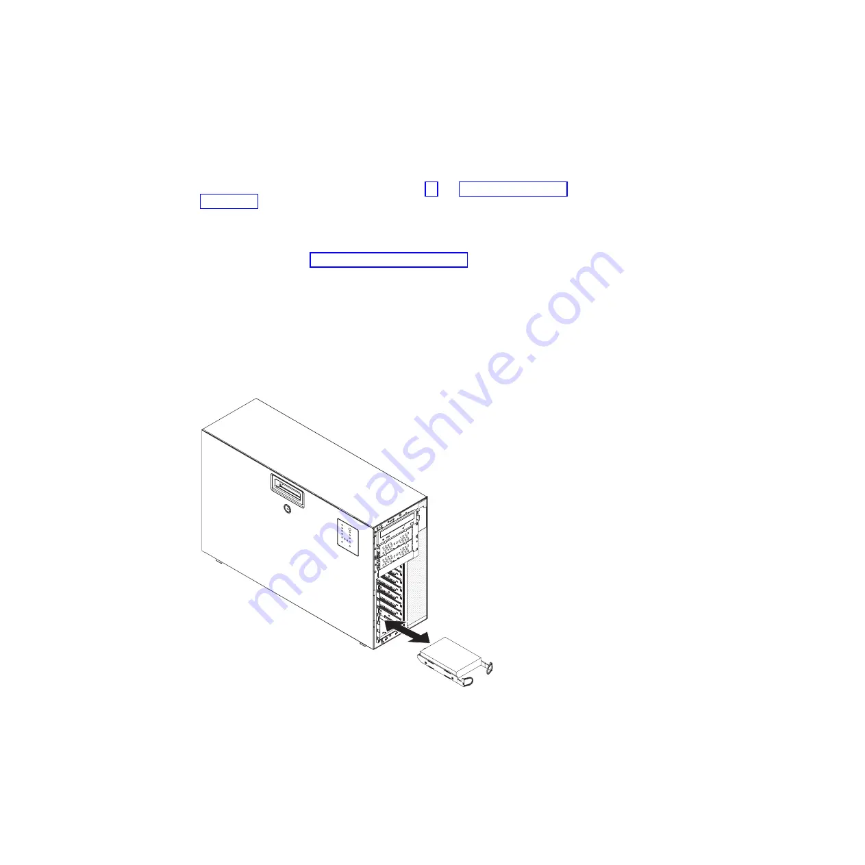
Installing


a


simple-swap


hard


disk


drive


Attention:


Simple-swap


hard


disk


drives


are


not


hot-swappable.


Disconnect


all


power


from


the


server


before


removing


or


installing


a


simple-swap


hard


disk


drive.


To


install


a


simple-swap


hard


disk


drive,


complete


the


following


steps.


1.


Read


the


safety


information


that


begins


on


page


vii


and


“Installation


guidelines”


on


page


95.


2.


Turn


off


the


server


and


all


attached


devices;


then,


disconnect


all


power


cords


and


external


cables.


3.


Unlock


the


side


cover.


4.


Remove


the


bezel


(see


“Removing


the


bezel”


on


page


98).


5.


Touch


the


static-protective


package


that


contains


the


drive


to


any


unpainted


metal


surface


on


the


server;


then,


remove


the


drive


from


the


package


and


place


it


on


a


static-protective


surface.


6.


Align


the


drive


assembly


with


the


guide


rails


in


the


bay.


7.


Pull


the


loops


of


the


drive


assembly


toward


each


other;


then,


carefully


slide


the


drive


assembly


into


the


drive


bay


until


it


stops


and


release


the


loops.


Note:


Do


not


release


the


loops


on


the


drive


assembly


until


it


is


completely


seated.


8.


Closed


the


bezel.


9.


Lock


the


side


cover.


10.


Reconnect


the


external


cables


and


power


cords;


then,


turn


on


the


attached


devices


and


turn


on


the


server.


Chapter


4.


Removing


and


replacing


server


components


115

Содержание System x3400 Type 7973

Страница 1: ...System x3400 Types 7973 7974 7975 and 7976 Problem Determination and Service Guide...

Страница 2: ......

Страница 3: ...System x3400 Types 7973 7974 7975 and 7976 Problem Determination and Service Guide...

Страница 4: ...and the Warranty and Support Information document on the IBM xSeries Documentation CD Third Edition Ocotober 2006 Copyright International Business Machines Corporation 2006 All rights reserved US Gove...

Страница 5: ...ST 17 POST beep codes 18 No beep symptoms 21 Error logs 22 Viewing error logs from the Configuration Setup Utility program 23 Viewing the BMC log from the diagnostic programs 23 POST error codes 24 Ch...

Страница 6: ...ng a hot swap power supply 116 Installing a hot swap power supply 118 Removing a memory module 119 Installing a memory module 120 Removing a hot swap fan 122 Installing a hot swap fan 123 Removing the...

Страница 7: ...e ServerGuide Setup and Installation CD 166 Using the Configuration Setup Utility program 166 Using the RAID configuration programs 166 Using ServeRAID Manager 171 Using the Boot Menu program 172 Conf...

Страница 8: ...vi System x3400 Types 7973 7974 7975 and 7976 Problem Determination and Service Guide...

Страница 9: ...tuotteen lue turvaohjeet kohdasta Safety Information Avant d installer ce produit lisez les consignes de s curit Vor der Installation dieses Produkts die Sicherheitshinweise lesen Prima di installare...

Страница 10: ...aged CRT face or a bulging or leaking capacitor v Mechanical hazards such as loose or missing hardware To inspect the product for potential unsafe conditions complete the following steps 1 Make sure t...

Страница 11: ...chanical inspection work near power supplies or remove or install main units v Before you work on the equipment disconnect the power cord If you cannot disconnect the power cord have the customer powe...

Страница 12: ...n document For example if a caution statement begins with a number 1 translations for that caution statement appear in the Safety Information document under statement 1 Be sure to read all caution and...

Страница 13: ...quipment when there is evidence of fire water or structural damage v Disconnect the attached power cords telecommunications systems networks and modems before you open the device covers unless instruc...

Страница 14: ...When laser products such as CD ROMs DVD drives fiber optic devices or transmitters are installed note the following v Do not remove the covers Removing the covers of the laser product could result in...

Страница 15: ...ower control button on the device and the power switch on the power supply do not turn off the electrical current supplied to the device The device also might have more than one power cord To remove a...

Страница 16: ...omponent that has this label attached There are no serviceable parts inside these components If you suspect a problem with one of these parts contact a service technician Statement 10 CAUTION Do not p...

Страница 17: ...Statement 11 CAUTION The following label indicates sharp edges corners or joints nearby Statement 17 CAUTION The following label indicates moving parts nearby Safety xv...

Страница 18: ...xvi System x3400 Types 7973 7974 7975 and 7976 Problem Determination and Service Guide...

Страница 19: ...server v Installation Guide This printed document contains instructions for setting up the server and basic instructions for installing some options v User s Guide This document is in Portable Documen...

Страница 20: ...document The caution and danger statements that appear in this document are also in the multilingual Safety Information document which is on the IBM System x3400 Documentation CD Each statement is num...

Страница 21: ...0 1000 Ethernet controller on the system board with RJ 45 Ethernet port v Six port Serial ATA controller v Integrated RAID capability SATA HostRAID v Remote Supervisor Adapter II SlimLine v Two serial...

Страница 22: ...ne Types 7975 and 7976 Depending on the server model some features might not be available or some specifications might not apply See the User s Guide for more detail information about the specificatio...

Страница 23: ...in v Weight 20 kg 42 lb to 34 kg 75 lb depending upon configuration Integrated functions v Baseboard management controller BMC or onboard service processor v Broadcom 5721 10 100 1000 Ethernet control...

Страница 24: ...and connectors on the front of the hot swap server models USB connectors Power control button Front information panel CD or DVD eject button CD or DVD drive activity LED green System power LED Hard d...

Страница 25: ...D is off it does not mean that there is no electrical power in the server The LED might be burned out To remove all electrical power from the server you must disconnect the power cords from the electr...

Страница 26: ...When this green LED is flashing it indicates that the drive is in use When the drive is removed this LED also is visible on the SAS backplane next to the drive connector The backplane is the printed...

Страница 27: ...net 10 100 for Remote Supervisor Adapter II SlimLine USB 3 NMI button AC power LEDs DCpower LEDs Power cords Serial 2 COM 2 The following illustration shows the connectors on the rear of the non hot s...

Страница 28: ...rial 1 connector Connect a 9 pin serial device to this connector Parallel connector Connect a parallel device to this connector Video connector Connect a monitor to this connector USB connectors Conne...

Страница 29: ...ing illustration shows the internal connectors on the system board 1 2 3 4 5 6 7 8 9 10 11 12 DIMM LEDs Main power Power Power Front panel USB tape Primary IDE Front USB Microprocessor 1 Microprocesso...

Страница 30: ...he system board Mouse Keyboard Serial 1 COM 1 Parallel Video USB 4 RJ45 Ethernet 10 100 1000 RJ45 Ethernet 10 100 for Remote Supervisor Adapter II SlimLine USB 3 NMI button Serial 2 COM 2 1 2 3 4 5 6...

Страница 31: ...4 DIMM 9 DIMM 3 DIMM 8 DIMM 2 DIMM 7 DIMM 1 Microprocessor 1 Microprocessor 2 VRM Battery ServeRAID adapter Slot 4 PCI X 64 bit 133 MHz Slot 5 PCI X 64 bit 133 MHz Slot 6 PCI 32 bit 33 MHz Slot 1 PCI...

Страница 32: ...error LED Slot 3 error LED Slot 4 error LED Slot 5 error LED Slot 6 error LED Microprocessor mismatch LED DIMM error LEDs 1 through 12 Microprocessor 1 error LED Microprocessor 2 error LED VRM error...

Страница 33: ...ion 1 Boot block v When this switch is on 1 this is normal mode v When this switch is toggled to On this enables the system to recover if the BIOS code becomes damaged See Recovering from a BIOS updat...

Страница 34: ...16 System x3400 Types 7973 7974 7975 and 7976 Problem Determination and Service Guide...

Страница 35: ...stem errors quickly See Error LEDs on page 55 for more information v Diagnostic programs messages and error messages The diagnostic programs are the primary method of testing the major components of t...

Страница 36: ...0 Types 7973 7974 7975 and 7976 on page 87 to determine which components are customer replaceable units CRU and which components are field replaceable units FRU v If an action step is preceded by Trai...

Страница 37: ...r test failed Trained service technician only Replace the system board 2 1 3 Primary interrupt mask register test failed Trained service technician only Replace the system board 2 1 4 Secondary interr...

Страница 38: ...eseat the DIMMS then restart the server Important In some memory configurations the 3 3 3 beep code might sound during POST followed by a blank monitor screen If this occurs and the Boot Fail Count op...

Страница 39: ...placeable units CRU and which components are field replaceable units FRU v If an action step is preceded by Trained service technician only that step must be performed only by a trained service techni...

Страница 40: ...t you can find current errors more easily Important After you complete a repair or correct an error clear the BMC log to turn off the system error LED on the front of the server Entries that are writt...

Страница 41: ...gnostic programs The BMC log contains the same information whether it is viewed from the Configuration Setup Utility program or from the diagnostic programs For information about using the diagnostic...

Страница 42: ...t failure Trained service technician only Replace the system board 151 Real time clock error 1 Reseat the battery 2 Replace the following components one at a time in the order shown restarting the ser...

Страница 43: ...board 175 Service processor flash code damaged or not loaded 1 Restart the server 2 Update the optional Remote Supervisor Adapter II SlimLine firmware see Updating the firmware on page 165 3 Replace t...

Страница 44: ...r with an incorrect password Restart the server and enter the administrator password then run the Configuration Setup Utility program and change the power on password 196 Processor cache mismatch 1 Ma...

Страница 45: ...order shown restarting the server each time a Keyboard b Trained service technician only System board 303 Keyboard controller failure 1 Reseat the keyboard 2 Replace the keyboard 3 Trained service te...

Страница 46: ...ician only that step must be performed only by a trained service technician Error code Description Action 1762 Fixed disk configuration error 1 Run the Configuration Setup Utility program select Load...

Страница 47: ...e x 5 Reseat the following components depending on the server model v Hot swap and non hot swap models a Hard disk drive x b Hard disk drive x cable c Optional adapter cable d SAS SATA backplane v Sim...

Страница 48: ...orrect change them 4 If all memory resources are being used remove an adapter to make memory available to the adapter Disabling the BIOS on the adapter should correct the error See the documentation t...

Страница 49: ...CI Express slot or device remove that device 3 Reseat each adapter 4 Replace the following components one at a time in the order shown restarting the server each time a Adapter b Trained service techn...

Страница 50: ...if no LEDs are lit reseat each adapter one at a time restarting the server each time to isolate the failing adapter 3 Replace the following components one at a time in the order shown restarting the...

Страница 51: ...wing components depending on the server model v Hot swap and non hot swap models a Hard disk drive b Hard disk drive cable c Optional adapter cable d SAS SATA backplane v Simple swap models a Hard dis...

Страница 52: ...estarting the server each time 4 Trained service technician only Replace the system board 8603 Pointing device error 1 Reseat the pointing device 2 Replace the following components one at a time in th...

Страница 53: ...m board 00019701 Processor 1 failed the built in self test BIST 1 Trained service technician only Reseat microprocessor 1 2 Replace the following components one at a time in the order shown restarting...

Страница 54: ...e technician only Replace microprocessor 2 01298101 Bad update data for processor 1 1 Make sure that all microprocessors have the same cache size see Using the Configuration Setup Utility program on p...

Страница 55: ...seat the following components depending on the server model v Hot swap and non hot swap models a Hard disk drive b Hard disk drive cable c Optional adapter cable d SAS SATA backplane v Simple swap mod...

Страница 56: ...r s Guide on the IBM System x3400 Documentation CD 2 Run the hard disk drive diagnostic tests 3 Reseat the following components depending on the server model v Hot swap models a Hard disk drive b Hard...

Страница 57: ...programs you must determine whether the failing server is part of a shared hard disk drive cluster two or more servers sharing external storage devices If it is part of a cluster you can run all diag...

Страница 58: ...ay of the operating system desktop 3 Did a single beep sound and are there readable instructions on the main menu or was a POST error code displayed v Yes Find the beep code or error code in POST beep...

Страница 59: ...nents are customer replaceable units CRU and which components are field replaceable units FRU v If an action step is preceded by Trained service technician only that step must be performed only by a t...

Страница 60: ...solved v See Chapter 3 Parts listing System x3400 Types 7973 7974 7975 and 7976 on page 87 to determine which components are customer replaceable units CRU and which components are field replaceable u...

Страница 61: ...ained service technician Symptom Action Not all drives are recognized by the hard disk drive diagnostic test the Fixed Disk Test Remove the drive that is indicated by the diagnostic tests then run the...

Страница 62: ...ed in the Action column until the problem is solved v See Chapter 3 Parts listing System x3400 Types 7973 7974 7975 and 7976 on page 87 to determine which components are customer replaceable units CRU...

Страница 63: ...ouse or pointing device cable is securely connected to the server v If you are using a PS 2 mouse or pointing device the keyboard and mouse or pointing device cables are not reversed v The mouse or po...

Страница 64: ...matically disabled a DIMM when it detected a problem 2 Check the POST error log for error message 289 v If a DIMM was disabled by a system management interrupt SMI replace the DIMM 3 Run memory diagno...

Страница 65: ...Reseat the following components a Trained service technician only Microprocessor b VRM 4 Trained service technician only If there is no indication of which microprocessor has failed isolate the error...

Страница 66: ...tor is turned on and the brightness and contrast controls are adjusted correctly v No beep codes sound when the server is turned on Important In some memory configurations the 3 3 3 beep code might so...

Страница 67: ...r Attention Moving a color monitor while it is turned on might cause screen discoloration Move the device and the monitor at least 305 mm 12 in apart and turn on the monitor Notes a To prevent diskett...

Страница 68: ...rs eserver serverproven compat us v You followed the installation instructions that came with the device and the device is installed correctly v You have not loosened any other installed devices or ca...

Страница 69: ...e correct type of DIMMs v The DIMMs are correctly seated v A POST beep code did not sound indicating a memory initialization error v The LEDs on the power supply do not indicate a problem v The microp...

Страница 70: ...cian only that step must be performed only by a trained service technician Symptom Action The number of serial ports that are identified by the operating system is less than the number of installed se...

Страница 71: ...ServerGuide Setup and Installation CD label for a list of supported operating system versions The operating system cannot be installed the option is not available Make sure that the operating system...

Страница 72: ...USB device does not work 1 Run USB diagnostics see Running the diagnostic programs on page 58 2 Make sure that v The correct USB device driver is installed v The operating system supports USB devices...

Страница 73: ...perating system is shut down Many errors are first indicated by a lit system error LED on the control panel assembly of the server If this LED is lit one or more LEDs elsewhere in the server might als...

Страница 74: ...f internal components This information can often provide enough information to correct the error Power supply LEDs The following minimum configuration is required for the server to start v One micropr...

Страница 75: ...ne power supply at a time Lit Off Off DC source or power supply power problem 1 Make sure that the power supply is connected to the power backplane 2 Remove and replace one power supply at a time 3 Vi...

Страница 76: ...ructions on the screen When you are diagnosing hard disk drives select SCSI Attached Disk Test for the most thorough test Select Fixed Disk Test for any of the following situations v You want to run a...

Страница 77: ...rning The test could not be run There was no failure of the hardware that was being tested but there might be a hardware failure elsewhere or another problem prevented the test from running for exampl...

Страница 78: ...0 Types 7973 7974 7975 and 7976 on page 87 to determine which components are customer replaceable units CRU and which components are field replaceable units FRU v If an action step is preceded by Trai...

Страница 79: ...technician only Replace the system board 015 xxx 001 Failed USB test Trained service technician only Replace the system board 015 xxx 198 Remote Supervisor Adapter II SlimLine installed or USB device...

Страница 80: ...e b ServeRAID controller 3 Replace the components listed in step 2 one at a time in the order shown restarting the server each time 035 230 001 Battery Low Replace the battery module on the RAID contr...

Страница 81: ...1 Hot swap power supply 2 Hot swap power backplane 3 Replace the following components depending on your model v Hot swap power supply v Trained service technician only Non hot swap power supply 089 xx...

Страница 82: ...stem Management Failed Unable to communicate with ASM It may be busy Run the test again 1 Update the firmware BIOS service processor and diagnostics see Updating the firmware on page 165 2 Run the dia...

Страница 83: ...mponents listed in step 4 one at a time in the order shown restarting the server each time 166 201 000 ISMP indicates I2C errors on bus X Trained service technician only Replace the system board 166 2...

Страница 84: ...hnician only System board 166 201 008 ISMP indicates I2C errors on bus M1 1 Reseat the DIMM 2 Replace the following components one at a time in the order shown restarting the server each time a DIMM b...

Страница 85: ...est again 2 Reseat the SAS SATA hard disk drive backplane cables 3 Replace the following components one at a time in the order shown restarting the server each time a SAS SATA hard disk drive backplan...

Страница 86: ...Replace the following components one at a time in the order shown restarting the server each time a DIMM b Trained service technician only System board 180 xxx 007 Failed power supply fan LED test 1 R...

Страница 87: ...ng the server each time a Trained service technician only Microprocessor n b Trained service technician only System board 215 xxx 000 Failed CD or DVD test 1 Run the test again with a different CD or...

Страница 88: ...server model in the order shown restarting the server each time v Hot swap models a Hard disk drive b SAS SATA controller cable c SAS SATA backplane d SAS SATA controller v Simple swap and non hot sw...

Страница 89: ...ed only by a trained service technician Error code Description Action 305 xxx xxx Failed video monitor test 1 Reseat the monitor cable 2 Replace the following components one at a time in the order sho...

Страница 90: ...s see Removing an adapter on page 102 1 2 3 4 5 6 7 8 9 10 11 12 DIMM LEDs Boot block Clear CMOS 5 Toggle the boot block recovery switch to On 6 Replace any adapters that you removed see Installing an...

Страница 91: ...n the server The following table describes the function of each switch on the system board Table 4 System board switches Switch number Description 1 Boot block v When this switch is on 1 this is norma...

Страница 92: ...de Error Data Error Data The following table describes the possible system error log messages and suggested actions to correct the detected problems v Follow the suggested actions in the order in whic...

Страница 93: ...Supervisor Adapter SlimLine connector on the system board see System board option connectors on page 13 for the location of the connector 2 Reseat the cable both ends from the Remote Supervisor Adapte...

Страница 94: ...tion only Flash of x via z failed for user z z Information only Flash succeeded for x address y Information only Hard Drive x Fault 1 Run the diagnostics programs 2 Replace hard disk drive x 3 Replace...

Страница 95: ...access attempt failed Information only Remote access attempt failed Invalid userid or password received Userid is x from WEB browser at IP yyy yyy yyy yyy Information only Remote access attempt failed...

Страница 96: ...ervice technician only Power supply cables on the system board 2 Trained service technician only Replace the system board System is over recommended voltage for 1 5V CPU 1 Reseat the following compone...

Страница 97: ...e technician only Power supply cables on the system board 2 Trained service technician only Replace the system board System shut off due to system board under temperature 1 Make sure that the fans hav...

Страница 98: ...Power supply cables on the system board 2 Trained service technician only Replace the system board System shutoff due to 1 5V CPU under voltage 1 Reseat the following components a Hot swap power supp...

Страница 99: ...ined service technician only Microprocessor b Trained service technician only System board System under recommended voltage for 12v 1 Reseat the following components a Hot swap power supplies if any a...

Страница 100: ...ower problems can be difficult to solve For example a short circuit can exist anywhere on any of the power distribution buses Usually a short circuit will cause the power subsystem to shut down becaus...

Страница 101: ...h the speed and duplex mode of the hub v Check the Ethernet controller LEDs on the rear panel of the server These LEDs indicate whether there is a problem with the connector cable or hub The Ethernet...

Страница 102: ...external devices v Surge suppressor device on the server v Modem printer mouse and non IBM devices v Each adapter v Hard disk drives v Memory modules The minimum configuration requirement is two 512 M...

Страница 103: ...rted before v Diagnostic program type and version level v Hardware configuration print screen of the system summary v BIOS code level v Operating system type and version level You can solve some probl...

Страница 104: ...86 System x3400 Types 7973 7974 7975 and 7976 Problem Determination and Service Guide...

Страница 105: ...check for an updated parts listing on the Web complete the following steps 1 Go to http www ibm com support 2 Under Search technical support type 7973 7974 7975 or 7976 depending on your model and cli...

Страница 106: ...type 7973 7974 optional 39M4507 1 Hard disk drive 250 GB type 7973 7974 optional 39M4511 1 Hard disk drive 500 GB type 7973 7974 optional 39M4517 1 Hard disk drive 36 GB type 7975 7976 optional 39R73...

Страница 107: ...atsink type 7973 7974 model 42x type 7975 7976 models 42x 4Ax 41Y4275 20 Microprocessor 1 87 GHz with heatsink type 7973 7974 model 52x type 7975 7976 models 52x 5Ax 41Y4276 20 Microprocessor 2 0 GHz...

Страница 108: ...rive optional 42C0951 ServeRAID 8k l type 7975 7977 25R8079 System board tray 41Y9077 Bottom cover optional 41Y9069 Side top cover 39Y8360 Alcohol wipe 59P4739 Adapter NetXtreme 1000 optional 39Y6081...

Страница 109: ...ptional 26K7363 Keylock with random keys optional 26K7364 Remote supevisory adapter 2 optional 13N0833 Mouse optical wheel 39Y9875 Mouse 3 button USB optical optional 40K9203 PRO 1000 GT server ethern...

Страница 110: ...in these countries and regions 39Y8200 China 39Y8128 Australia Fiji Kiribati Nauru New Zealand Papua New Guinea 39Y6558 Afghanistan Albania Algeria Andorra Angola Armenia Austria Azerbaijan Belarus Be...

Страница 111: ...Bolivia Brazil Caicos Islands Canada Cayman Islands Costa Rica Colombia Cuba Dominican Republic Ecuador El Salvador Guam Guatemala Haiti Honduras Jamaica Japan Mexico Micronesia Federal States of Net...

Страница 112: ...94 System x3400 Types 7973 7974 7975 and 7976 Problem Determination and Service Guide...

Страница 113: ...to lift an object that you think is too heavy for you If you have to lift a heavy object observe the following precautions Make sure that you stand safely without slipping Distribute the weight of th...

Страница 114: ...e server without the air baffle installed Operating the server without the air baffle might cause the microprocessor to overheat v The microprocessor socket always contains a microprocessor and heat s...

Страница 115: ...joints pins or exposed circuitry v Do not leave the device where others can handle and damage it v While the device is still in its static protective package touch it to an unpainted metal part on the...

Страница 116: ...e bezel To remove the bezel complete the following steps 1 Read the safety information that begins on page vii and Installation guidelines on page 95 2 Unlock the side cover 3 Position your finger on...

Страница 117: ...lace the bezel complete the following steps 1 Insert the tabs on the bezel into the slots on the server chassis 2 Rotate the bezel toward the server until it snaps in place Chapter 4 Removing and repl...

Страница 118: ...e 95 2 If you are replacing a non hot swap component turn off the server and all attached devices then disconnect all power cords and external cables 3 Unlock the side cover 4 Press the cover release...

Страница 119: ...les adapters and other components are installed and seated correctly and that you have not left loose tools or parts inside the server Also make sure that all internal cables are correctly routed 2 In...

Страница 120: ...ention bracket also 6 Remove the expansion slot screw at the rear of the adapter if screws were used 7 Carefully grasp the adapter by its top edge or upper corners and pull the adapter from the server...

Страница 121: ...on clip and rotate the retention brackets to the open unlocked position If you are installing a full length adapter Open the front retention bracket retention clip and rotate the front adapter retenti...

Страница 122: ...te the rear and front adapter retention brackets to the closed position 8 Connect required cables to the adapter Route cables so that they do not block the flow of air from the fans 9 Install the side...

Страница 123: ...ive bays in the server The following illustration shows the location of the drive bays in the hot swap server models Bay 1 Bay 2 Bay 3 Bay 4 Bay 5 Bay 6 Bay 7 Bay 8 Bay 9 Bay 10 Bay 11 The following i...

Страница 124: ...the chassis v Non hot swap models lift up the power supply cage handle and pull the power supply cage assembly all the way up until the retainer latch locks the cage in place on the chassis 5 Remove...

Страница 125: ...such as CD ROMs DVD drives fiber optic devices or transmitters are installed note the following v Do not remove the covers Removing the covers of the laser product could result in exposure to hazardou...

Страница 126: ...at come with the drive to set jumpers or switches if there are any Note You might find it easier to install the new drive from the front and then attach the cables 6 Align the holes on the blue optica...

Страница 127: ...swap models a Remove the hot swap power supply Press down on the orange release lever and pull the power supply out of the bay using the handle b Lift up the power supply cage handle and pull the powe...

Страница 128: ...e retainer latch locks the cage in place on the chassis v Non hot swap models lift up the power supply cage handle and pull the power supply cage assembly all the way up until the retainer latch locks...

Страница 129: ...nstalled in each drive bay To remove a hot swap SAS or hot swap SATA hard disk drive complete the following steps 1 Read the safety information that begins on page vii and Installation guidelines on p...

Страница 130: ...kit To install a hot swap hard disk drive complete the following steps 1 Unlock the side cover 2 Remove the side cover see Removing the side cover on page 100 3 Remove the bezel see Removing the bezel...

Страница 131: ...at the controller is identifying the drive If the green hard disk drive activity LED is flashing this indicates that the drive is in use Note If the server is configured for RAID operation using an op...

Страница 132: ...and all attached devices then disconnect all power cords and external cables 3 Unlock the side cover 4 Remove the side cover see Removing the side cover on page 100 5 Remove the bezel see Removing th...

Страница 133: ...ving the bezel on page 98 5 Touch the static protective package that contains the drive to any unpainted metal surface on the server then remove the drive from the package and place it on a static pro...

Страница 134: ...s Statement 8 CAUTION Never remove the cover on a power supply or any part that has the following label attached Hazardous voltage current and energy levels are present inside any component that has t...

Страница 135: ...n page 95 2 Disconnect the power cord from the power supply that is to be removed 3 Press down on the orange release latch and pull the power supply out of the bay using the handle Release latch Power...

Страница 136: ...ly into the bay guides Power supply filler Release latch Power supply 3 Using the handle push the power supply toward the front of the chassis until it locks into place 4 Connect one end of the power...

Страница 137: ...way up until the retainer latch locks the cage in place on the chassis v Non hot swap models lift up the power supply cage handle and pull the power supply cage assembly all the way up until the reta...

Страница 138: ...ower cords and external cables 2 Unlock and remove the side cover see Removing the side cover on page 100 3 Rotate the power supply cage assembly out of the chassis v Hot swap models a Remove the hot...

Страница 139: ...remove the DIMM and then reinsert it 8 Reconnect any cables that were disconnected during removal 9 Press the power supply cage release tab and rotate the power supply cage assembly into the chassis...

Страница 140: ...2 Unlock and remove the side cover see Removing the side cover on page 100 3 Take your finger and slide the orange release tab on the fan in the direction indicated by the arrow on the top of the fan...

Страница 141: ...e hot swap fan to any unpainted metal surface on the server then remove the fan from the package and place it on a static protective surface 3 Align the fan over the bay in which you want to install t...

Страница 142: ...de the rear system fan cage assembly to the left to release it from the mounting tabs on the chassis then remove it from the server 6 If you are instructed to return the fan cage assembly follow all p...

Страница 143: ...on page 11 for the location of the rear fan assembly connector Rear Fan Connector 4 Install the side cover see Installing the side cover on page 101 5 Lock the side cover 6 Reconnect the external cabl...

Страница 144: ...ls a Remove the hot swap power supply Press down on the orange release lever and pull the power supply out of the bay using the handle b Lift up the power supply cage handle and pull the power supply...

Страница 145: ...u are instructed to return the fan cage assembly follow all packaging instructions and use any packaging materials for shipping that are supplied to you Chapter 4 Removing and replacing server compone...

Страница 146: ...sis and press down firmly until the fan cage assembly is seated firmly in place 3 Press the power supply cage release tab and rotate the power supply cage assembly into the chassis until it locks in p...

Страница 147: ...the cable see System board internal connectors on page 11 for the location of the front USB connector 6 Press down and hold the release tab on the top of the front USB housing then tilt the top of the...

Страница 148: ...on the attached devices and turn on the server Removing the rear adapter retention bracket To remove the rear adapter retention bracket complete the following steps 1 Turn off the server and all atta...

Страница 149: ...Position the rear adapter retention bracket so that the hole in one of the hinge points is aligned with the hinge pin on the chassis then place the hinge pin through the hole on the chassis 3 Rotate...

Страница 150: ...the bracket in the opposite direction to release the other side of the bracket and remove the adapter retention bracket from the server Installing the front adapter retention bracket To install the fr...

Страница 151: ...board internal connectors on page 11 6 Remove the battery a Use a fingernail to press the top of the battery clip away from the battery The battery pops up when it is released b Use your thumb and ind...

Страница 152: ...ecurely 3 Install the side cover see Installing the side cover on page 101 4 Lock the side cover if it was unlocked during removal 5 Reconnect the external cables and power cords then turn on the atta...

Страница 153: ...en and close the clips gently 3 Open the retaining clip on each end of the ServeRAID 8k l adapter connector 4 Touch the static protective package containing the ServeRAID 8k l adapter to any unpainted...

Страница 154: ...to replace the ServeRAID 8k adapter reinstall the battery pack mounting screws into the holes in the chassis otherwise set them aside for future use Installing the ServeRAID 8k adapter To install the...

Страница 155: ...l cable from the Simple swap SATA backplate connector on the system board and connector it to the Hot swap SAS SATA 1 connector on the system board See System board internal connectors on page 11 for...

Страница 156: ...side cover see Removing the side cover on page 100 4 Rotate the power supply cage assembly out of the chassis v Hot swap models a Remove the hot swap power supply Press down on the orange release lev...

Страница 157: ...DIMM air duct complete the following steps 1 Let the locator pins on the end of the air duct hang over the end of the power supply cage 2 Slide the air duct down the power supply cage till the pins lo...

Страница 158: ...r supply cage assembly all the way up until the retainer latch locks the cage in place on the chassis v Non hot swap models lift up the power supply cage handle and pull the power supply cage assembly...

Страница 159: ...out approximately half way start turning it downward and pull it out of the chassis Release latch Control panel assembly 11 If you are instructed to return the control panel assembly follow all packa...

Страница 160: ...drive on page 107 for more information 5 Reinstall the front fan cage assembly see Installing the front system fan cage assembly on page 128 6 Press the power supply cage release tab and rotate the po...

Страница 161: ...les 3 Unlock and remove the side cover see Removing the side cover on page 100 4 Remove the hot swap power supplies see Removing a hot swap power supply on page 116 Note It might be helpful to lay the...

Страница 162: ...supply cage to the chassis then lift the cage off the chassis Power supply assembly Power supply retaining screws 7 If you are instructed to return the power supply cage follow all packaging instruct...

Страница 163: ...orresponding screw holes on the rear of the chassis Support the cage while you install the three screws to secure the pivot bracket on the power supply cage to the chassis Power supply assembly Power...

Страница 164: ...he simple swap backplate complete the following steps 1 Read the safety information that begins on page vii and Installation guidelines on page 95 2 Turn off the server and all attached devices then d...

Страница 165: ...sconnect the combination signal power cable from the simple swap backplate 8 Lift up on the spring release latch on the side of the drive cage and rotate the simple swap backplate away from the drive...

Страница 166: ...ap hard disk drives that were removed from the hard disk drive cage see Installing a simple swap hard disk drive on page 115 5 Reinstall the front fan cage assembly see Installing the front system fan...

Страница 167: ...power supply cage handle and pull the power supply cage assembly all the way up until the retainer latch locks the cage in place on the chassis v Non hot swap models lift up the power supply cage han...

Страница 168: ...model reinstall the hot swap power supplies see Installing a hot swap power supply on page 118 9 Install the side cover see Installing the side cover on page 101 10 Lock the side cover 11 Reconnect t...

Страница 169: ...k and remove the side cover see Removing the side cover on page 100 Note It might be helpful to lay the server on its side for the remainder of this procedure 4 Disconnect the cables from the power su...

Страница 170: ...sis Save the screws to use when you install the replacement power supply Power supply assembly Power supply retaining screws 7 If you are instructed to return the power supply follow all packaging ins...

Страница 171: ...tem board and all internal components 6 Install the side cover see Installing the side cover on page 101 7 Lock the side cover 8 Reconnect the external cables and power cords then turn on the attached...

Страница 172: ...t swap power supply docking cable assembly complete the following steps 1 Position the hot swap power supply docking cable assembly from the inside the server and insert it in the power supply docking...

Страница 173: ...chassis v Non hot swap models lift up the power supply cage handle and pull the power supply cage assembly all the way up until the retainer latch locks the cage in place on the chassis 6 Remove the...

Страница 174: ...elease the microprocessor release lever by pressing down on the end moving it to the side and slowly releasing it to the open up position Microprocessor release lever fully open Microprocessor bracket...

Страница 175: ...sor to any unpainted metal surface on the server Then remove the microprocessor from the package 2 Remove the protective cover tape or label from the surface of the microprocessor socket if any is pre...

Страница 176: ...cking lever is in the fully open position Important Be careful when you handle the microprocessor and heat sink Do not contaminate the thermal material between them b Slide the bottom edge of the heat...

Страница 177: ...ease The thermal grease must be replaced whenever the heat sink has been removed from the top of the microprocessor and is going to be reused or when debris is found in the grease To replace damaged o...

Страница 178: ...ed approximately half 0 22 mL of the grease will remain in the syringe 6 Install the heat sink onto the microprocessor as described in Installing a microprocessor and heat sink on page 157 160 System...

Страница 179: ...he chassis 6 Remove the front fan cage assembly see Removing the front system fan cage assembly on page 126 7 Note where each cable is connected then disconnect all cables from the system board 8 Remo...

Страница 180: ...ide and carefully lift the system board out of the server Release lever Handle Handle 12 If you are instructed to return the system board follow all packaging instructions and use any packaging materi...

Страница 181: ...talling an adapter on page 103 3 Reconnect any cables to the system board that you disconnected during removal 4 Reinstall the front fan cage assembly see Installing the front system fan cage assembly...

Страница 182: ...164 System x3400 Types 7973 7974 7975 and 7976 Problem Determination and Service Guide...

Страница 183: ...You can select to update the VPD code during the BIOS code update procedure Configuring the server The ServerGuide Setup and Installation CD provides software setup tools and installation tools that...

Страница 184: ...tips about the operating system and adapter e Start the setup and hardware configuration programs f Start the operating system installation You will need your copy of the operating system CD Using the...

Страница 185: ...RAID level 0 and level 1 when two drives are installed When the maximum four drives are installed RAID level 10 is also supported Note In addition when the maximum four drives and the optional ServeRA...

Страница 186: ...ces are on the IBM ServeRAID Configuration Utility menu v Array Configuration Utility Select this choice to create manage or delete arrays add or delete a hot spare drive or initialize drives v Serial...

Страница 187: ...is part of the BIOS code The Adaptec RAID Configuration Utility program adds RAID functionality to the integrated SATA controller The integrated Serial ATA SATA controller comes disabled by default Y...

Страница 188: ...ys to highlight it and press Enter Creating a RAID array To use the Adaptec RAID Configuration Utility program to configure a RAID level 1 array complete the following steps 1 Start the Adaptec RAID C...

Страница 189: ...Manager is also available from the Help menu For information about a specific object in the ServeRAID Manager tree select the object and click Actions Hints and tips Configuring the controller By runn...

Страница 190: ...information To change the configuration click Back 9 Click Apply when you are asked whether you want to apply the new configuration click Yes The configuration is saved in the controller and in the ph...

Страница 191: ...y operates at that rate and mode You do not have to set any jumpers or configure the controller However you must install a device driver to enable the operating system to address the controller To fin...

Страница 192: ...174 System x3400 Types 7973 7974 7975 and 7976 Problem Determination and Service Guide...

Страница 193: ...EITHER EXPRESS OR IMPLIED INCLUDING BUT NOT LIMITED TO THE IMPLIED WARRANTIES OF NON INFRINGEMENT MERCHANTABILITY OR FITNESS FOR A PARTICULAR PURPOSE Some states do not allow disclaimer of express or...

Страница 194: ...a registered trademark of The Open Group in the United States and other countries Java and all Java based trademarks and logos are trademarks of Sun Microsystems Inc in the United States other countr...

Страница 195: ...s no representation or warranties regarding non IBM products and services that are ServerProven including but not limited to the implied warranties of merchantability and fitness for a particular purp...

Страница 196: ...s s travers l Union europ enne Conform ment la directive ladite tiquette pr cise que le produit sur lequel elle est appos e ne doit pas tre jet mais tre r cup r en fin de vie In accordance with the Eu...

Страница 197: ...States go to http www ibm com ibm environment products batteryrecycle shtml or contact your local waste disposal facility In the United States IBM has established a return process for reuse recycling...

Страница 198: ...onnectors or by unauthorized changes or modifications to this equipment Unauthorized changes or modifications could void the user s authority to operate the equipment This device complies with Part 15...

Страница 199: ...as been tested and found to comply with the limits for Class A Information Technology Equipment according to CISPR 22 European Standard EN 55022 The limits for Class A equipment were derived for comme...

Страница 200: ...182 System x3400 Types 7973 7974 7975 and 7976 Problem Determination and Service Guide...

Страница 201: ...umentation that comes with the IBM systems also describes the diagnostic tests that you can perform Most systems operating systems and programs come with documentation that contains troubleshooting pr...

Страница 202: ...p www ibm com planetwide for support telephone numbers In the U S and Canada call 1 800 IBM SERV 1 800 426 7378 Hardware service and support Important When you call for service you will be asked to pr...

Страница 203: ...168 ServeRAID controller 171 ServerGuide Setup and Installation CD 166 summary window 172 configuration utility IBM ServeRAID starting 168 Configuration Setup Utility program 166 configuring the serv...

Страница 204: ...LED 8 10 Ethernet continued controller configuring 173 high performance modes 173 link status LED 8 10 modes 173 Ethernet connector 10 Ethernet controller troubleshooting 83 expansion slots 3 5 expres...

Страница 205: ...onfiguring 169 intermittent problems 44 internal connectors 11 internal drives installing 105 removing 105 K keyboard connector 10 keyboard problems 44 L LEDs CD drive activity 8 DVD drive activity 8...

Страница 206: ...Serial ATA creating 170 RAID configuration programs 167 recovering BIOS update failure 72 redundant array of independent disks RAID Adaptec HostRAID 167 Serial ATA HostRAID 169 ServeRAID Manager 171 r...

Страница 207: ...external connectors 12 installing 163 internal connectors 11 jumpers 15 LEDs 14 option connectors 13 removing 161 system event log BMC 22 system event error log 22 system reliability 96 system specif...

Страница 208: ...W weight 3 4 5 190 System x3400 Types 7973 7974 7975 and 7976 Problem Determination and Service Guide...

Страница 209: ......

Страница 210: ...Part Number 31R2197 Printed in USA 1P P N 31R2197...

Отзывы: