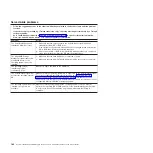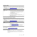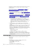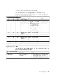
When LEDs are lit to indicate an error, they remain lit when the server is turned off,
provided that the server is still connected to power and the power supply is
operating correctly.
Before you work inside the server to view light path diagnostics LEDs, read the
safety information that begins on page “Safety” on page vii and “Handling
static-sensitive devices” on page 277.
If an error occurs, view the light path diagnostics LEDs in the following order:
1. Read the safety information that begins on page vii and “Installation guidelines”
2. Turn off the server and peripheral devices and disconnect all power cords.
3. If the system-board tray is installed in a chassis, remove it (see “Removing the
system-board tray from a 2U chassis” on page 279).
4. Remove the system-board tray cover (see “Removing the system-board tray
5. Look at the operator information panel on the front of the server.
v
If the check log LED is lit, it indicates that an error or multiple errors have
occurred. The sources of the errors cannot be isolated or concluded by
observing the light path diagnostics LEDs directly. A further investigation into
IMM2 system-event log or system-error log might be required.
v
If the system-error LED is lit, it indicates that an error has occurred; go to
step 2.
6. Remove the server cover and look inside the server for lit LEDs. Certain
components inside the server have LEDs that are lit to indicate the location of a
problem.
v
Remind button:
Press this button to place the system-error LED/check log LED
on the front information panel into Remind mode. By placing the system-error
LED indicator in Remind mode, you acknowledge that you are aware of the last
failure but will not take immediate action to correct the problem. In Remind mode,
the system-error LED flashes every 2 seconds until one of the following
conditions occurs:
– All known errors are corrected.
– The server is restarted.
– A new error occurs, causing the system-error LED to be lit again.
v
Reset button:
Press this button to reset the server and run the power-on
self-test (POST). You might have to use a pen or the end of a straightened paper
clip to press the button. The Reset button is in the lower-right corner of the light
path diagnostics panel.
Power-supply LEDs
The following minimum configuration is required for the DC LED on the power
supply to be lit:
v
Power supply
v
Power cord
The following minimum configuration is required for the server to start:
v
One microprocessor in microprocessor socket 1
v
One 2 GB DIMM on the system board
v
One power supply
v
Power cord
v
Four cooling fans (two for each thermal zone)
188
System x iDataPlex dx360 M4 Types 7912 and 7913: Problem Determination and Service Guide
Содержание System x iDataPlex dx360 M4 7912
Страница 1: ...System x iDataPlex dx360 M4 Types 7912 and 7913 Problem Determination and Service Guide...
Страница 2: ......
Страница 3: ...System x iDataPlex dx360 M4 Types 7912 and 7913 Problem Determination and Service Guide...
Страница 22: ...4 System x iDataPlex dx360 M4 Types 7912 and 7913 Problem Determination and Service Guide...
Страница 278: ...260 System x iDataPlex dx360 M4 Types 7912 and 7913 Problem Determination and Service Guide...
Страница 292: ...274 System x iDataPlex dx360 M4 Types 7912 and 7913 Problem Determination and Service Guide...
Страница 392: ...374 System x iDataPlex dx360 M4 Types 7912 and 7913 Problem Determination and Service Guide...
Страница 399: ......
Страница 400: ...Part Number 46W8218 Printed in USA 1P P N 46W8218...

