11.
On the new system backplane, remove the socket cover from a system processor socket.
12.
Prepare the system processor module for removal.
a.
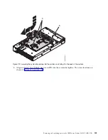
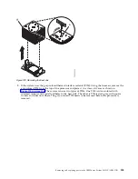
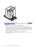
Using the supplied removal tool (part number 01AF101), align the beveled corner (A) of the tool
over the beveled corner of the system processor module as shown in Figure 126 on page 108.
b.
Lower the tool over the system processor module by ensuring the two guide pins (C) are inserted
into the alignment holes (B) on each side of the tool.
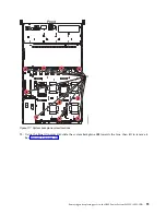
Figure 125. Removing dust and debris from the system processor module area
Removing and replacing parts in the IBM Power System S822LC (8335-GTB)
107
Содержание S822LC
Страница 1: ...Power Systems Servicing the IBM Power System S822LC 8335 GTB IBM ...
Страница 2: ......
Страница 3: ...Power Systems Servicing the IBM Power System S822LC 8335 GTB IBM ...
Страница 16: ...xiv Power Systems Servicing the IBM Power System S822LC 8335 GTB ...
Страница 204: ...188 Power Systems Servicing the IBM Power System S822LC 8335 GTB ...
Страница 242: ...226 Power Systems Servicing the IBM Power System S822LC 8335 GTB ...
Страница 243: ......
Страница 244: ...IBM ...


