j.
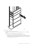
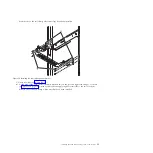
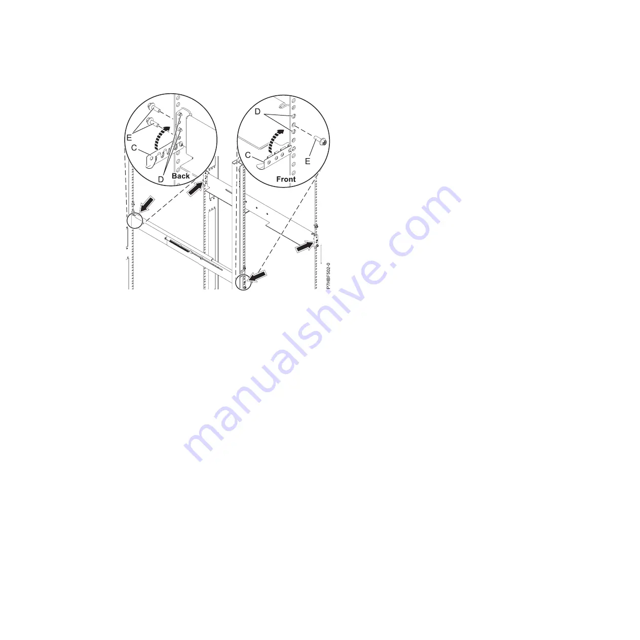
Use one M5 screw
(E)
, below the top rail pin
(D)
, to secure the right rail to the front of the rack.
See the previous figure.
k.
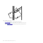
Locate the remaining marks made previously on the front Electronic Industries Alliance (EIA)
strips of the rack cabinet. Each side contains one mark. Insert a nut clip at these two locations.
l.
From the back of the rack cabinet, locate the remaining marks made previously on the rear EIA
strips. Each side contains three marks. Insert a nut clip these six locations.
7.
Install the expansion unit onto the rails as follows:
a.
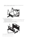
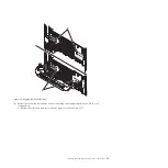
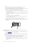
Remove the four thumb screws
(B)
that are used to secure the shipping cover
(A)
to the rear of the
expansion unit, as shown in the following figure. Remove the shipping cover.
Note:
The shipping cover is secured to the expansion unit by two thumb screws on the top of the
cover and one thumb screw on each side.
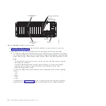
Figure 5. Attaching the rails
8
Power Systems: Installing the 5802 and 5877 expansion units
Содержание Power System 5802
Страница 1: ...Power Systems Installing the 5802 and 5877 expansion units GI11 4307 09...
Страница 2: ......
Страница 3: ...Power Systems Installing the 5802 and 5877 expansion units GI11 4307 09...
Страница 6: ...iv Power Systems Installing the 5802 and 5877 expansion units...
Страница 38: ...26 Power Systems Installing the 5802 and 5877 expansion units...
Страница 52: ...40 Power Systems Installing the 5802 and 5877 expansion units...
Страница 62: ...50 Power Systems Installing the 5802 and 5877 expansion units...
Страница 63: ......
Страница 64: ...Part Number 00L5079 Printed in USA GI11 4307 09 1P P N 00L5079...


