System-board switches and jumpers
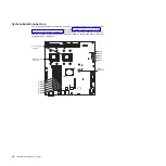
The following illustration shows the locations of the switches on the system board
that relate to selected system functions. See the
Problem Determination and
Service Guide
for more information about using switches and jumpers on the
system board.
Switch 4 (SW4)
Switch 3 (SW3)
Switch 2 (SW2)
Switch 1 (SW1)
Table 2. System-board switches
Switch
number
Switch
(button) description
1
NMI
. When this button is pressed, it issues a non-maskable interrupt (NMI) to the server. This button
is functional only when power is connected to the server and the server is running.
2
Clear CMOS
. When this button is pressed, it clears the CMOS data, which clears the user and
supervisor passwords. This button is functional when no power is connected to the system-board tray.
3
Power-on
. This button is not used for the dx320 server.
4
Reset
. This button is not used for the dx320 server.
Chapter 2. Components, features, and controls
11
Содержание iDataPlex dx320 6385
Страница 1: ...System x iDataPlex dx320 Types 6385 and 6388 User s Guide...
Страница 2: ......
Страница 3: ...System x iDataPlex dx320 Types 6385 and 6388 User s Guide...
Страница 12: ...x IBM iDataPlex dx320 User s Guide...
Страница 28: ...16 IBM iDataPlex dx320 User s Guide...
Страница 56: ...44 IBM iDataPlex dx320 User s Guide...
Страница 59: ......
Страница 60: ...Part Number 90Y5674 Printed in USA 1P P N 90Y5674...


