


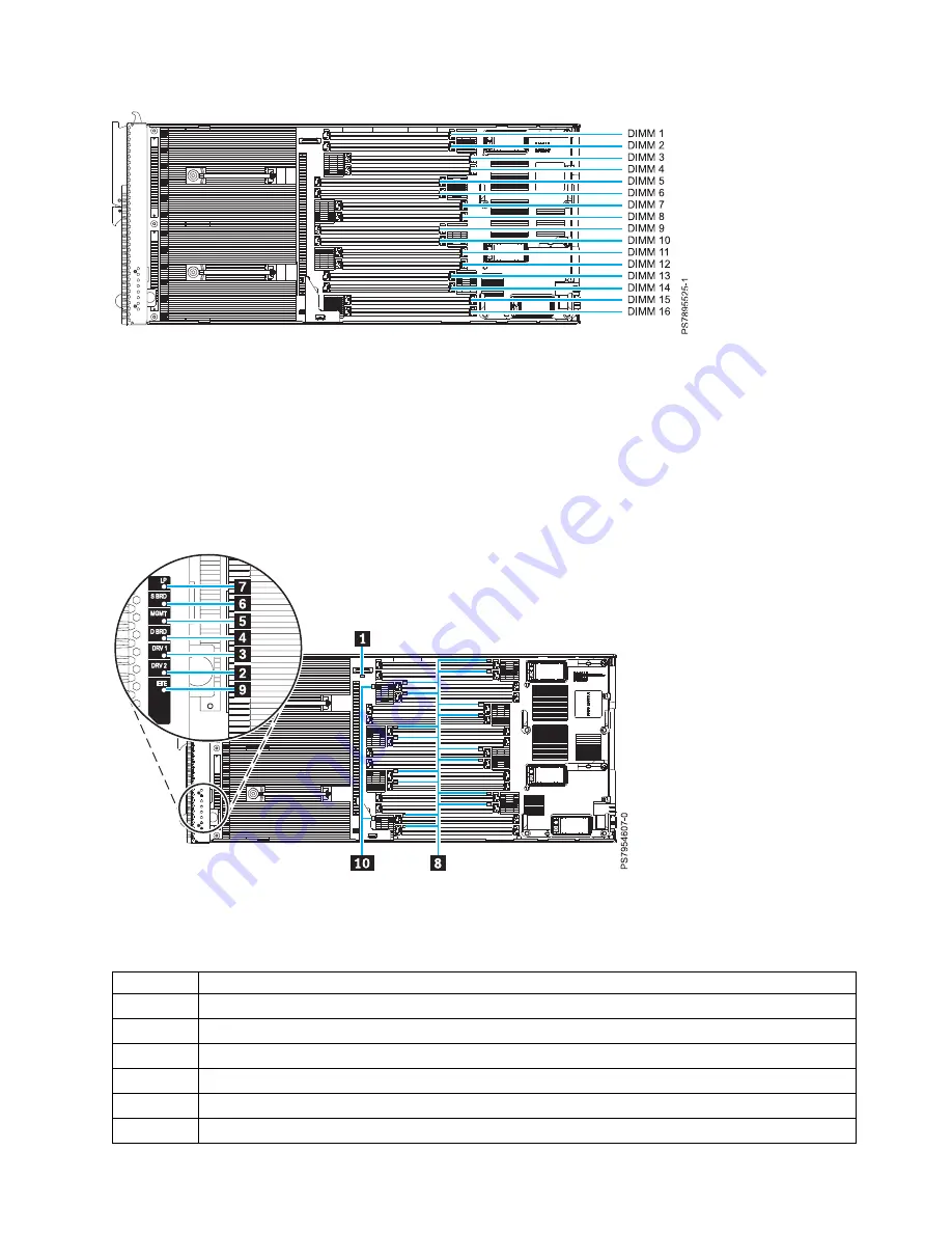
System-board LEDs
Use the illustration of the LEDs on the system board to identify a light emitting diode (LED).
Press and hold the front power-control button to see any light path diagnostic LEDs that were turned on
during error processing. Use the following figure to identify the failing component.
The following figure shows LEDs on the IBM Flex System p270 Compute Node.
The following table identifies the light path diagnostic LEDs.
Table 3. IBM Flex System p270 Compute Node LEDs
Callout
Unit LEDs
▌1▐
3 V lithium battery LED
▌2▐
DRV2 LED (HDD or SSD)
▌3▐
DRV1 LED (HDD or SSD)
▌4▐
Drive board LED (solid-state drive interposer, which is integrated in the cover)
▌5▐
Management card LED
▌6▐
System board LED
Figure 3. DIMM connectors for the IBM Flex System p270 Compute Node
Figure 4. LED locations on the system board of the IBM Flex System p270 Compute Node
Chapter 2. Power, controls, indicators, and connectors
13
Содержание Flex System p270 Compute Node
Страница 1: ...Power Systems IBM Flex System p270 Compute Node Installation and Service Guide IBM ...
Страница 2: ......
Страница 3: ...Power Systems IBM Flex System p270 Compute Node Installation and Service Guide IBM ...
Страница 38: ...26 Power Systems IBM Flex System p270 Compute Node Installation and Service Guide ...
Страница 40: ...28 Power Systems IBM Flex System p270 Compute Node Installation and Service Guide ...
Страница 110: ...98 Power Systems IBM Flex System p270 Compute Node Installation and Service Guide ...
Страница 498: ...486 Power Systems IBM Flex System p270 Compute Node Installation and Service Guide ...
Страница 509: ...Appendix Notices 497 ...
Страница 510: ...IBM Printed in USA ...