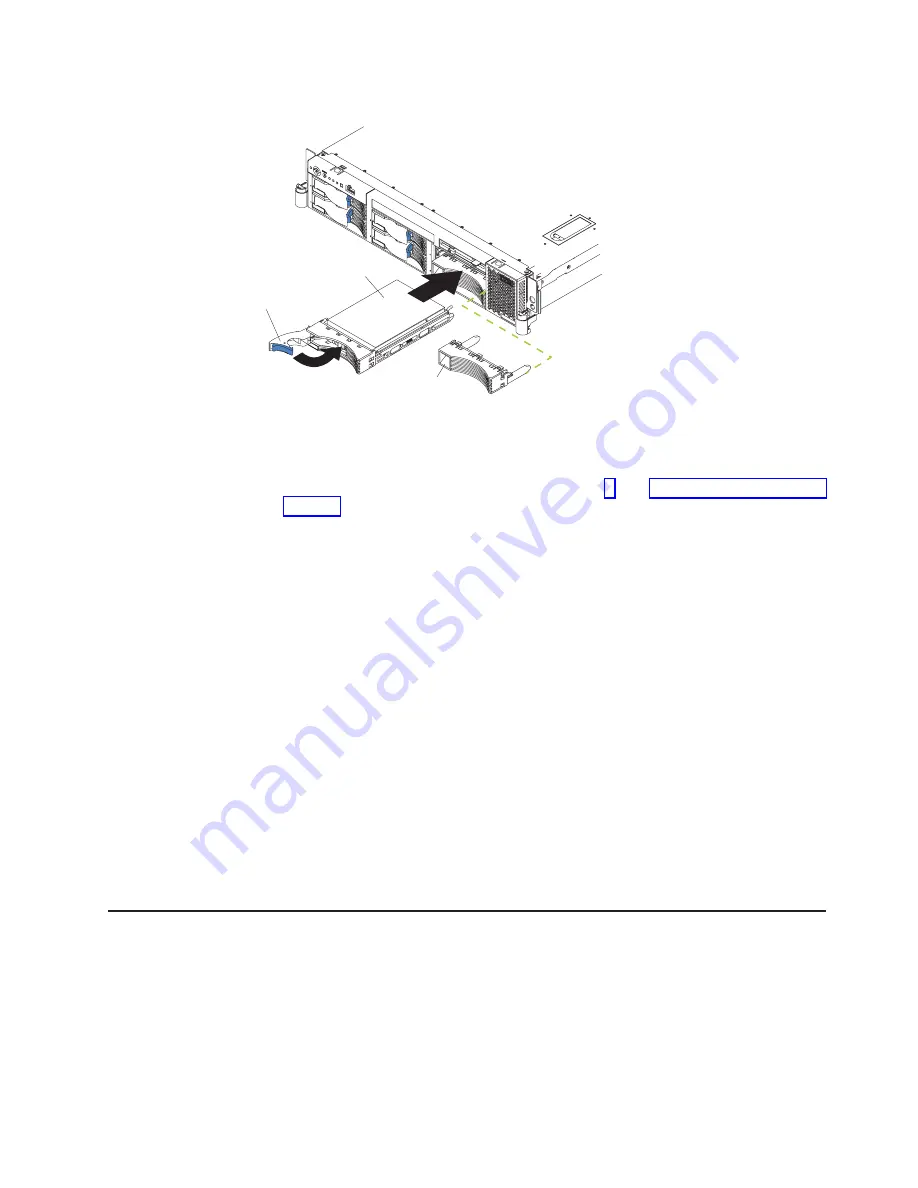
The following illustration shows how to install a hot-swap hard disk drive.
Filler panel
Drive-tray assembly
Drive handle
Complete the following steps to install a drive in a hot-swap bay.
Attention:
To maintain proper system cooling, do not operate the server for more
than 10 minutes without either a drive or a filler panel installed in each bay.
1. Read the safety information beginning on page v, and “Installation guidelines” on
2. Remove the filler panel from one of the empty hot-swap bays by inserting your
finger into the depression at the left side of the filler panel and pulling it away
from the server.
3. Install the hard disk drive in the hot-swap bay:
a. Ensure that the tray handle is open (that is, perpendicular to the drive).
b. Align the drive assembly with the guide rails in the bay.
c. Gently push the drive assembly into the bay until the drive stops.
d. Push the tray handle to the closed (locked) position.
e. Check the hard disk drive status LED to verify that the hard disk drive is
operating properly.
If the amber hard disk drive status LED for a drive is lit continuously, that
individual drive is faulty and needs to be replaced. If the green hard disk
drive activity LED is flashing, the drive is being accessed.
Note:
If you have a RAID configuration on your server using the integrated
SCSI controller with RAID capabilities, or if your server has a RAID
adapter installed, you might need to reconfigure your disk arrays after
installing hard disk drives. See the RAID documentation on the IBM
xSeries Documentation
CD for information about RAID adapters.
Installing memory modules
The following notes describe the types of dual inline memory modules (DIMMs) that
your server supports and other information that you must consider when installing
DIMMs:
v
The system board contains four DIMM connectors and supports two-way memory
interleaving.
v
The DIMM options available for your server are 256 MB, 512 MB, 1 GB, and 2
GB.
Chapter 2. Installing options
23
Содержание Eserver 345 Series
Страница 1: ...IBM xSeries 345 Type 8670 Option Installation Guide SC88 P919 00 ERserver...
Страница 2: ......
Страница 3: ...IBM xSeries 345 Type 8670 Option Installation Guide SC88 P919 00 ERserver...
Страница 55: ...The following illustration shows a video connector 1 5 11 15 Chapter 3 Input output connectors 43...
Страница 56: ...44 IBM xSeries 345 Type 8670 Option Installation Guide...
Страница 64: ...52 IBM xSeries 345 Type 8670 Option Installation Guide...
Страница 68: ...56 IBM xSeries 345 Type 8670 Option Installation Guide...
Страница 69: ......
Страница 70: ...Part Number 88P9190 Printed in U S A SC88 P919 00 1P P N 88P9190...


