background image


Chapter 5.  Installing options

 83

Keyboard port

One keyboard port connector is located on the rear of your server.

Note:

If you attach a standard (non-USB) keyboard to the keyboard connector, the 
USB ports and devices will be disabled during the power-on self-test (POST).

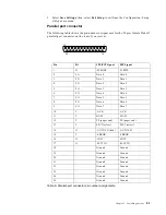
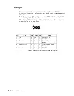
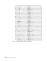
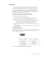
The following table shows the pin-number assignments for the keyboard connector 
on the rear of your server.

Auxiliary-device (pointing device) port

The I/O board has one auxiliary-device port that supports a mouse or other pointing 
device.

The following table shows the pin-number assignments for the auxiliary-device 
connector on the rear of your server.

Pin

I/O

Signal

1

I/O

Data

2

N/A

Reserved

3

N/A

Ground

4

N/A

+5 V dc

5

I/O

Keyboard clock

6

N/A

Reserved

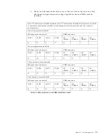
Table 8. Keyboard connector pin-number assignments. 

6

4

2

1

3

5

6

4

2

1

3

5

Содержание eServer 250 xSeries

Страница 1: ...User s Reference xSeries 250...

Страница 2: ......

Страница 3: ...IBM IBM xSeries 250 User s Reference SC21 P902 00...

Страница 4: ...formation in Appendix A Product warranties and notices on page 149 First Edition March 2001 Copyright International Business Machines Corporation 2001 All rights reserved US Government Users Restricte...

Страница 5: ...ices available from the SCSISelect menu 20 Chapter 4 Using the ServerGuide CDs 23 Features at a glance 24 Setup and configuration overview 25 System Partition 26 Typical NOS installation 26 Setting up...

Страница 6: ...g or changing the serial port assignments 87 Serial port connectors 87 Universal Serial Bus ports 88 USB cables and hubs 88 USB port connectors 88 Ethernet port 89 Configuring the Ethernet controller...

Страница 7: ...IBM Statement of Limited Warranty 149 Part 1 General Terms 149 Part 2 Country unique Terms 151 Notices 157 Edition notice 157 Processing date data 158 Trademarks 158 Important notes 158 Electronic em...

Страница 8: ...vi IBM xSeries 250 User s Reference...

Страница 9: ...kirjanen ennen kuin asennat t m n tuotteen Avant de proc der l installation de ce produit lisez le manuel Safety Information Vor Beginn der Installation die Brosch re mit Sicherheitshinweisen lesen Pr...

Страница 10: ...instalar este produto leia o folheto Informa es sobre Seguran a Antes de instalar este producto lea la Informaci n de Seguridad L s s kerhetsinformationen innan du installerar den h r produkten Safety...

Страница 11: ...ny equipment when there is evidence of fire water or structural damage Disconnect the attached power cords telecommunications systems networks and modems before you open the device covers unless instr...

Страница 12: ...ired by local ordinances or regulations Statement 3 CAUTION When laser products such as CD ROMs DVD drives fiber optic devices or transmitters are installed note the following Do not remove the covers...

Страница 13: ...ON The power control button on the device and the power switch on the power supply do not turn off the electrical current supplied to the device The device also might have more than one power cord To...

Страница 14: ...xii IBM xSeries 250 User s Reference...

Страница 15: ...rformance ease of use reliability and expansion capabilities were key considerations during the design of your server These design features make it possible for you to customize the system hardware to...

Страница 16: ...pending upon configuration Integrated functions Advanced System Management processor Dual Ultra2 LVD SCSI controller one external port one internal port One 10BASE T 100BASE TX AMD Ethernet controller...

Страница 17: ...sing an innovative approach to SMP Your server supports up to four Pentium III Xeon microprocessors Your server comes with one microprocessor installed you can install additional microprocessors to en...

Страница 18: ...switched to the redundant NIC This switching occurs without data loss and without user intervention IBM ServerGuide CDs The ServerGuide CDs included with your server provide programs to help you set u...

Страница 19: ...ration and Power Interface ACPI level Power on self test POST Power supply redundancy monitoring Predictive Failure Analysis PFA alerts Processor serial number access Redundant Ethernet capabilities w...

Страница 20: ...ivity light When this green light is flashing the drive is being accessed CD ROM eject load button Press this button to eject or retract the CD ROM tray CD ROM drive in use light When this light is on...

Страница 21: ...processor is initializing therefore the power control button does not respond If the server is turned on and a power failure occurs the server will start automatically when power is restored If the se...

Страница 22: ...rver in standby mode Note After turning off the server wait at least five seconds before you press the power control button to turn on the server again You might need to press and hold the power contr...

Страница 23: ...net speed is 10 Mbps Processor activity lights One or more of these green lights are on when there is microprocessor activity The number of lights that are on indicates the number of microprocessors w...

Страница 24: ...10 IBM xSeries 250 User s Reference...

Страница 25: ...or so the top of the screen is at or slightly below eye level Place the monitor at a comfortable viewing distance usually 51 to 61 cm 20 to 24 in and position it so you can view it without having to t...

Страница 26: ...icient Also make sure that the vented air is not blowing on someone else Electrical outlets and cable lengths The location of electrical outlets and the length of power cords and cables that connect t...

Страница 27: ...n The ServerGuide CDs also contain a collection of application programs which you can install after your server is up and running See Chapter 4 Using the ServerGuide CDs on page 23 for more detailed i...

Страница 28: ...s summary screen You cannot edit the fields This choice appears on both the full and limited Configuration Setup Utility menus System Information Select this choice to display information about your s...

Страница 29: ...etup Utility main menu You can implement two levels of password protection Power on Password Select this choice to set or change a power on password See Using passwords on page 18 for more information...

Страница 30: ...t this choice to modify settings that control features of the core chip set Attention Do not make changes here unless directed to do so by an IBM authorized service representative Cache Control Select...

Страница 31: ...t the bank that you want to enable then use the arrow keys to select Enable System Service Processor Settings Select this choice to enable or disable power supply redundancy monitoring Event Error Log...

Страница 32: ...password Keep a record of your password in a secure place When a power on password is set POST does not complete until you enter the password If you forget the power on password you can regain access...

Страница 33: ...oices are available on the Configuration Setup Utility main menu Administrator password No password is required to start the system Enter the password to access the Configuration Setup Utility program...

Страница 34: ...When prompted select either channel A or channel B 4 Use the arrow keys to select a choice from the menu Press Esc to return to the previous menu Press the F5 key to switch between color and monochrom...

Страница 35: ...ssages as each drive starts After the drive that you want to view or format starts press Ctrl A Format Disk Attention The Low Level Format program erases all data and programs Select this choice to pe...

Страница 36: ...22 IBM xSeries 250 User s Reference...

Страница 37: ...available you can purchase an update package For details see the ServerGuide Updates form that comes with your server library or go to the ServerGuide fulfillment Web site at http www ibm com pc coup...

Страница 38: ...led hardware options and provides updated device drivers for most adapters and devices Setup and Installation CD continued Creates a Setup Replication Diskette for replicating setup selections for oth...

Страница 39: ...es the option of duplicating your setup selections to other servers that are the same model If you select the Custom Configuration method the following programs are optional If you select the Express...

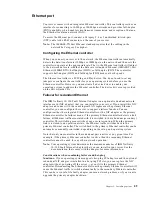
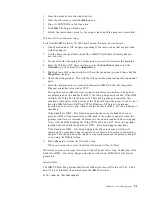
Страница 40: ...ures and functions can vary with different versions of the ServerGuide software After you have completed the setup process the operating system installation program starts You will need your copy of t...

Страница 41: ...llations This feature supports systems running Windows 2000 Windows NT Server 4 0 and Red Hat Linux Installing your NOS without ServerGuide If you have already configured the server hardware and you d...

Страница 42: ...ure that there are no duplicate SCSI IDs or IRQ assignments Ensure that the hard disk drive is connected properly The operating system installation program continuously loops Free up more space on the...

Страница 43: ...support this function For complete information about installing or removing a hot swap or hot plug component see the information provided in the detailed procedures in this document The blue color on...

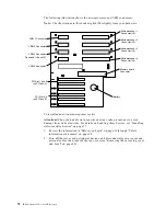
Страница 44: ...30 IBM xSeries 250 User s Reference Microprocessor Terminator card Memory module Shuttle I O board Memory board Shuttle cover VRM Fan assembly 3 Fan assembly 2 Fan assembly 4...

Страница 45: ...onent locations The following illustration shows the location of the input output connectors on the I O board Note The illustrations in this document might differ slightly from your hardware Power bac...

Страница 46: ...trations in this document might differ slightly from your hardware Processor board LEDs The following illustration shows the location of the LEDs Microprocessor 2 error LED Cr3 Microprocessor 1 error...

Страница 47: ...f the connectors Microprocessor 2 Connector J3 Microprocessor 1 Connector J2 Microprocessor 3 Connector J4 Microprocessor 4 Connector J5 Battery VRM 1 Connector VRM 4 Connector VRM 3 Connector Reserve...

Страница 48: ...ROM page swap jumper block J56 Power on password override jumper block J48 Battery Advanced System Management Processor reset jumper block J59 Power on control jumper block J23 3 3 V standby power fo...

Страница 49: ...nnector 13 J13 Connector 14 J14 Connector 15 J15 Connector 16 J16 Connector 2 J2 Connector 3 J3 Connector 4 J4 Connector 5 J5 Connector 6 J6 Connector 7 J7 Connector 8 J8 DIMM 1 error LED CR4 DIMM 9 e...

Страница 50: ...atch and so on Make sure that you have an adequate number of properly grounded electrical outlets for your server monitor and any other options that you intend to install Back up all important data be...

Страница 51: ...static sensitive devices in their static protective package until you are ready to install them To reduce the possibility of electrostatic discharge observe the following precautions Limit your moveme...

Страница 52: ...du installerer dette produkt Lue Safety Information kirjanen ennen kuin asennat t m n tuotteen Avant de proc der l installation de ce produit lisez le manuel Safety Information Vor Beginn der Install...

Страница 53: ...talar este produto leia o folheto Informa es sobre Seguran a Antes de instalar este producto lea la Informaci n de Seguridad L s s kerhetsinformationen innan du installerar den h r produkten Safety In...

Страница 54: ...ardware To remove the server top cover 1 Loosen the two captive screws on the back edge of the top cover 2 Slide the top cover slightly toward the rear of the server Lift the cover off the server and...

Страница 55: ...place Working with adapters You can install up to six PCI adapters in the expansion connectors on the processor board Your server comes with an integrated super video graphics array SVGA video control...

Страница 56: ...adapters Note Universal PCI adapters support both 3 3V and 5 0V operation Slots 1 and 2 support 3 3 V and universal non hot plug PCI adapters only Your server uses a rotational interrupt technique to...

Страница 57: ...see Handling static sensitive devices on page 37 1 Review the information in Before you begin on page 36 through Safety information statements on page 38 2 Remove the top cover see Removing the server...

Страница 58: ...lace the adapter component side up on a flat static protective surface 8 Install the adapter a Carefully grasp the adapter by its top edge or upper corners and align it with the expansion slot on the...

Страница 59: ...move the top cover see Removing the server top cover and bezel on page 40 4 Determine which expansion slot you will use for the adapter Note PCI slots 1 and 2 support non hot plug PCI adapters only 5...

Страница 60: ...board b Press the adapter firmly into the expansion slot Attention When you install an adapter in the server be sure that it is completely and correctly seated in the expansion slot Incomplete insert...

Страница 61: ...drive cables are labeled HDD To cable the ServeRAID adapter 1 Determine the number of SCSI channels that you want to use on the ServeRAID adapter If you are connecting to more than two SCSI channels y...

Страница 62: ...he retaining levers back to the unlocked position c Slide the shuttle toward the rear of the server until it stops Note It is not necessary to remove the shuttle from the server 7 Disconnect the SCSI...

Страница 63: ...ute one end of the SCSI cable through the cable retaining clips on the SCSI backplane Backplane Retention clips Retention clips Power cable connector Cable retaining clips Handle SCSI channel A connec...

Страница 64: ...SCSI backplane Attention When you route the SCSI cable do the following Do not block the ventilated space in front of the fan assembly Do not place the SCSI cable fold on top of the fan assembly Do no...

Страница 65: ...step 8 on page 49 and step 9 on page 50 for the second channel on the SCSI backplane The following illustration is a top down view that shows how to route two SCSI cables to the ServeRAID adapter in...

Страница 66: ...etaining levers from the notches on the chassis b Move the retaining levers toward the front of the server and secure the retaining levers in the horizontal locked position 12 If you have other option...

Страница 67: ...hannel B through a second optional SCSI cable One end of this second SCSI cable comes attached to the SCSI channel B connector on the backplane The other end of this cable is folded and restrained wit...

Страница 68: ...all of your internal hot swap hard disk drives to the same SCSI channel The following illustration shows the rear connectors on the optional SCSI repeater card as viewed from the rear of the server Ba...

Страница 69: ...el on page 40 3 If a ServeRAID adapter is installed in the server disconnect the SCSI cable from the adapter see Cabling example for the ServeRAID adapter on page 47 4 Disconnect the shuttle a Disenga...

Страница 70: ...e the repeater card option from the package Note If necessary refer to the documentation that comes with the repeater card option kit to assemble the repeater card option 9 Connect the repeater card o...

Страница 71: ...ect one end of this cable to the repeater card b Connect the other end of the cable to the SCSI channel B connector on the SCSI backplane c Secure both cable ends with the retention clips on the SCSI...

Страница 72: ...backplane guides with the corresponding slots on the server c Slide the SCSI backplane into the server d Connect one end of the SCSI cable to the repeater card e Make sure that the other end of the S...

Страница 73: ...onal information 13 Reinstall fan assembly 1 in the server 14 Reconnect the shuttle a Align the two shuttle pins with the holes on each side of the rear of the chassis and disengage the retaining leve...

Страница 74: ...y from your hardware Each hot swap drive has two indicator lights on the front of the server If the amber hard disk status light for a drive is lit continuously that individual drive is faulty and nee...

Страница 75: ...bays connect to the LVD SCSI backplane Your server comes with two SCSI channels on this backplane For more information see Using the LVD SCSI backplane on page 53 Some drives have a special interface...

Страница 76: ...tion in Before you begin on page 36 through Safety information statements on page 38 2 Remove the slim filler panel from one of the empty hot swap bays by inserting your finger into the depression at...

Страница 77: ...e left front bays Attention When you handle static sensitive devices take precautions to avoid damage from static electricity For details on handling these devices see Handling static sensitive device...

Страница 78: ...aining levers by pressing inward b Move the retaining levers back to the unlocked position c Slide the shuttle toward the rear of the server until it stops Note It is not necessary to remove the shutt...

Страница 79: ...er cables for removable media drives come installed in your server The connectors are keyed and can be inserted only one way 13 If you are installing another 5 25 inch drive do so now Otherwise contin...

Страница 80: ...and 1 GB when available DIMMs Note If you install 64 MB DIMMs they will not support the Chipkill memory function If you install 4 GB of memory some of the memory is reserved for system resources The a...

Страница 81: ...of 4 DIMMs Install DIMMs in these connectors First set shipped as standard J1 J5 J9 J13 2nd set J2 J6 J10 J14 3rd set J3 J 7 J11 J15 4th set J4 J8 J12 J16 Table 3 DIMM installation order Connector 1 J...

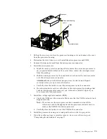
Страница 82: ...he processor housing cover and remove the cover from the processor housing 4 Remove the memory board assembly a Lift up on the memory board assembly and remove it from the server b Place the memory bo...

Страница 83: ...nnector Be sure that the retaining clips snap into the closed position 8 Install the memory board assembly a Hold the memory board assembly and align it over the memory board connector b Insert the me...

Страница 84: ...d type and the same clock speed Microprocessor internal and external clock frequencies must be identical 3 To order additional microprocessor options contact your IBM reseller or IBM marketing represe...

Страница 85: ...lled Microprocessor connectors VRM connectors J2 P1 J3 P2 J4 P3 J5 P4 J37 VRM 1 J38 VRM 2 J39 VRM 3 J41 VRM 4 X T T T X Two microprocessors installed Microprocessor connectors VRM connectors J2 P1 J3...

Страница 86: ...sitive devices on page 37 1 Review the information in Before you begin on page 36 through Safety information statements on page 38 2 Turn off the server and peripheral devices and disconnect all power...

Страница 87: ...e latches c Carefully close the latches to seat the microprocessor in the connector d Store the terminator card in a safe place in the static protective package that your new microprocessor comes in y...

Страница 88: ...ly bay you must disconnect the cable management arm You can reconnect the cable management arm after installing the power supply If you install or remove a power supply observe the following precautio...

Страница 89: ...ion 4 Slide the power supply into the chassis and close the handle 5 Plug one end of the power cord into the power supply then plug the other end of the cord into a properly grounded electrical outlet...

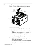
Страница 90: ...cedure b Press the fan release latch and lift the fan assembly out of the server c Slide the replacement fan assembly into the server The latch will snap into place and secure the fan in the server d...

Страница 91: ...g on the server Operating the server for extended periods of time over 30 minutes with the top cover removed might damage server components Installing the media bay bezel Refer to the following illust...

Страница 92: ...ns Reconfiguring the server When you start your server for the first time after you add or remove an internal option or an external SCSI device you might see a message telling you that the configurati...

Страница 93: ...llation and to connect it to the server Note If you are attaching a SCSI device see Setting SCSI IDs on page 85 for information about SCSI IDs and cables Input Output ports This section provides infor...

Страница 94: ...r change the parallel port assignment 1 Restart the server and watch the monitor screen 2 When the message Press F1 for Configuration Setup appears press F1 Note The Devices and I O Ports choice appea...

Страница 95: ...WRITE 2 I O Data 0 Data 0 3 I O Data 1 Data 1 4 I O Data 2 Data 2 5 I O Data 3 Data 3 6 I O Data 4 Data 4 7 I O Data 5 Data 5 8 I O Data 6 Data 6 9 I O Data 7 Data 7 10 I ACK ACK 11 I BUSY WAIT 12 I...

Страница 96: ...tomatically disable the integrated video controller The following table shows the pin number assignments for the 15 pin analog video connector on the rear of your server Pin Signal Pin Signal Pin Sign...

Страница 97: ...n number assignments for the keyboard connector on the rear of your server Auxiliary device pointing device port The I O board has one auxiliary device port that supports a mouse or other pointing dev...

Страница 98: ...15 SCSI devices You can use the external LVD SCSI channel connector on the rear of your server to connect different types of SCSI devices such as drives or printers SCSI cabling requirements If you p...

Страница 99: ...guration The hot swap drive backplane controls the SCSI IDs for the internal hot swap drive bays However when you attach a SCSI device to the external SCSI connector you must set a unique ID for the d...

Страница 100: ...48 Data P 15 Ground 49 Ground 16 DIFFSENS 50 Ground 17 Term power 51 Term power 18 Term power 52 Term power 19 Reserved 53 Reserved 20 Ground 54 Ground 21 Attention 55 Attention 22 Ground 56 Ground 2...

Страница 101: ...n Setup appears press F1 3 From the main menu select Devices and I O Ports then press Enter Note The Devices and I O Ports choice appears only on the full configuration menu If you set two levels of p...

Страница 102: ...uration Setup Utility program 3 Check to make sure that your NOS supports USB devices USB cables and hubs You need a 4 pin cable to connect devices to USB 1 or USB 2 If you plan to attach more than tw...

Страница 103: ...server If you install this NIC adapter and connect it to the same logical LAN segment as the primary Ethernet controller you can configure the server to support a failover function You can configure e...

Страница 104: ...r Windows NT 4 0 Solution 3 IBM Netfinity 10 100 Fault Tolerant Adapter device drivers Note The order of installation is important You must install the IBM Netfinity Hot Plug PCI for Windows NT Server...

Страница 105: ...BM Netfinity Hot Plug PCI for Windows NT Server 4 0 package is installed this checkbox will appear at the bottom of the Adapter Properties panel If you do not have the IBM Netfinity Hot Plug PCI for W...

Страница 106: ...ing table shows the pin number assignments for the RJ 45 connector These assignments apply to both 10BASE T and 100BASE TX devices Advanced System Management ports Your server has three communication...

Страница 107: ...n of input and output connectors Refer to the following illustration for an example of proper cable routing Ethernet USB1 USB2 Video Mouse Keyboard Ultra2 SCSI ASM Interconnect port B ASM Interconnect...

Страница 108: ...94 IBM xSeries 250 User s Reference...

Страница 109: ...ight emitting diodes LEDs to help you identify problems with server components These LEDs are part of the Light Path Diagnostics that are built into your server By following the path of lights you can...

Страница 110: ...enter Use the troubleshooting information provided with your server to determine the cause of the problem and the action to take Flash the latest levels of BIOS service processor diagnostics and RAID...

Страница 111: ...le a 1 2 4 beep code sounds like one beep a pause two consecutive beeps another pause and four more consecutive beeps The possible types of beep codes that your server might emit include the following...

Страница 112: ...ed an error on a video adapter If you are using the integrated video controller call for service If you are using an optional video adapter replace the failing video adapter One long and two short bee...

Страница 113: ...tor loading has failed 2 2 2 Keyboard controller test has failed 2 2 3 CMOS power failure and checksum checks have failed 2 2 4 CMOS configuration information validation has failed 2 3 2 Screen memory...

Страница 114: ...r resetting the server might cause this problem Action Start the Configuration Setup Utility program and verify that all settings are correct Use the Cache Control selection in the Advanced Setup menu...

Страница 115: ...er until you replace the battery However you must run the Configuration Setup Utility program and set the time and date and other custom settings each time you turn on the server 162 A change in devic...

Страница 116: ...ror If the problem persists call for service 175 A vital product data VPD error occurred Action Call for service 176 177 178 A security hardware error occurred Action Check for indications that someon...

Страница 117: ...If no error LED is on the error logs in the Configuration Setup Utility program might provide additional information on the memory error If the problem persists call for service 229 An error was dete...

Страница 118: ...or other pointing device turn off the server and disconnect that device Wait at least 5 seconds then turn on the server If the error message goes away replace the device 602 Invalid diskette boot reco...

Страница 119: ...re that the cable to the operator information panel is connected If the problem persists call for service 1302 Cable to Power and Reset pushbuttons not detected Action Make sure that the cable to the...

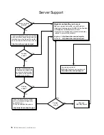
Страница 120: ...n Setup menu Go to step 3 No Follow the instructions on the screen to add the drive then save the changes and exit the Configuration Setup menu Restart the server 3 Is an operating system installed Ye...

Страница 121: ...to isolate the problem If the diagnostic tests do not find a problem and the POST error message remains call for service 00012000 Processor machine check Action 1 Update the system BIOS 2 If the prob...

Страница 122: ...e defective Action 1 Make sure that the I O address for the PCI adapter and all other adapters are set correctly in the Configuration Setup Utility program 2 If the I O port resource settings are corr...

Страница 123: ...ter one at a time and retest after each is reinstalled When an adapter fails replace it If the problem persists call for service 01295085 The ECC checking hardware test failed Action Call for service...

Страница 124: ...run at the same speed install microprocessors with identical speeds I9990301 A hard disk drive error occurred Action Call for service I9990305 POST could not find an operating system Action Install a...

Страница 125: ...case the server displays more than one error message Always follow the suggested action instructions for the first error message that appears The following sections contain the error codes that might...

Страница 126: ...the reason for the problem Text messages The diagnostic text message format is as follows Function Name Result test specific string where Function Name Is the name of the function being tested when t...

Страница 127: ...ll for service b The keyboard and mouse pointing device tests assume that a keyboard and mouse are attached to the server c If you run the diagnostic programs with no mouse attached to your server you...

Страница 128: ...System Management Processor ServeRAID and diagnostics microcode installed Code Function Result Text message Action 001 Core system Failed Processor board ECC Test Call for service System board 005 Vid...

Страница 129: ...structions If the problem persists call for service SCSI controller on system board failed register counter power test Call for service 035 ServeRAID Aborted Test setup error No ServeRAID adapter foun...

Страница 130: ...nfiguration error Logical drive on system board adapter Adapter in slot n memory allocation error where n is the slot number of the failing adapter Call for service On system board memory allocation e...

Страница 131: ...in socket id xyz is installed but not functioning where xyz identifies the microprocessor that is causing the error message Microprocessor in socket id xyz where xyz identifies the microprocessor tha...

Страница 132: ...mains call for service VRM corresponding to Microprocessor in socket id xyz is not installed where xyz identifies the microprocessor whose VRM is causing the error message Install a VRM If the problem...

Страница 133: ...2 If the problem remains replace the DIMM If the problem persists call for service Test setup error Corrupt BIOS in ROM If your server does not have the latest level BIOS installed update the BIOS to...

Страница 134: ...Test setup error Unknown hardware problem associated with microprocessor in socket id xyz where xyz identifies the microprocessor that is causing the error message Failed Microprocessor in socket ID x...

Страница 135: ...led for device n on adapter m where n is the number of the device and m is the adapter number The unload eject test failed for device n on adapter m where n is the number of the device and m is the ad...

Страница 136: ...service 305 Video monitor Any message Refer to the information that came with the monitor 405 Ethernet Failed In PCI slot n where n is the PCI slot number in which the failing Ethernet adapter is inst...

Страница 137: ...nable the modem 2 If the problem remains replace the modem If the problem persists call for service Failed Modem reset failed Replace the modem If the problem persists call for service No dial tone de...

Страница 138: ...ables and power cords then remove the cover 2 Locate jumper J56 on the processor board See Component locations on page 31 3 Move J56 to pins 1 and 2 to enable BIOS recovery mode 4 Insert the BIOS flas...

Страница 139: ...wer LEDs AC power LED DC power LED Description and action On On The power supply is on and operating correctly On Off There is a DC power problem Possible causes 1 The server is not turned on the powe...

Страница 140: ...ere is an AC power problem Possible causes 1 There is no AC power to the power supply Actions Verify that The electrical cord is properly connected to the server The electrical outlet functions proper...

Страница 141: ...for at least 20 seconds will turn off the system error LED On SMI A systems management event occurred Restart the server If the problem persists have the system serviced On NMI A nonmaskable interrupt...

Страница 142: ...If the error log indicates a problem with the integrated SCSI controller the Ethernet controller or video controller have your system serviced If the problem persists have the system serviced On DASD...

Страница 143: ...e system serviced On VRM One of the voltage regulator modules on the processor board has failed 1 Check the VRM error LEDs on the processor board 2 Turn off the server reseat the VRM indicated by the...

Страница 144: ...n OVER SPEC The server is drawing more power than the power supplies are rated for Either add a power supply or remove a device from the server On PS1 The first power supply has failed Replace the fir...

Страница 145: ...I and expansion enclosure documentation The SCSI expansion enclosure used to work but does not work now General problems Call for service Problems such as broken cover locks or indicator lights not wo...

Страница 146: ...replace the startup microprocessor If the problem remains call for service The server emits a continuous tone during POST Monitor Some IBM monitors have their own self tests If you suspect a problem...

Страница 147: ...bout obtaining ServerProven compatibility information from the World Wide Web 2 You followed the installation instructions that came with the option 3 The option is installed correctly 4 You have not...

Страница 148: ...fy that 1 Each port is assigned a unique address by the Configuration Setup Utility program and none of the serial ports are disabled Note The ASM Interconnect connector is the same as a serial port c...

Страница 149: ...vice Service Processor Manager reports a general monitor failure Software problem To determine if problems are caused by the software verify that 1 Your server has the minimum memory requirements need...

Страница 150: ...hernet controller How you test the Ethernet controller depends on which operating system you are using see the Ethernet controller device driver README file Ethernet controller troubleshooting chart Y...

Страница 151: ...ers Data is incorrect or sporadic Check the following Make sure that you are using Category 5 cabling when operating the server at 100 Mbps Make sure that the cables do not run close to noise inducing...

Страница 152: ...EEPROM information might be incorrect Action Make sure that the IRQ settings are correct in the Configuration Setup Utility program for information on setting the interrupt requests If the IRQ settin...

Страница 153: ...for service PCNTNW NW 091 The hardware configuration conflicts Explanation You tried to load a new frame type for the existing controller The hardware assumptions made in doing so are incorrect This...

Страница 154: ...setting Action None necessary message is for information only PermaNet Server No Secondary Adapter Found Grouping Mode is disabled Explanation The failover option requires an adapter that is compatib...

Страница 155: ...s enabled run the diagnostic programs pnt0 12 Device failed checksum test Explanation The driver cannot find an Ethernet controller Action Verify that the Ethernet controller is enabled If the Etherne...

Страница 156: ...und conflicts with other devices in the server Action Modify your hardware settings Run the NETCONFIG program to search for another Ethernet controller pnt0 23 add_intr_handler failed Vector already o...

Страница 157: ...IBM reseller or IBM marketing representative Note After you replace the battery you must reconfigure your server and reset the system date and time To replace the battery 1 Read the information in Bef...

Страница 158: ...he battery from under the battery clip d Ensure that the battery clip is touching the base of the battery socket by pressing gently on the clip 8 Insert the new battery a Tilt the battery so that you...

Страница 159: ...Questions Parts Information Technical Hints and Tips and Downloadable Files In addition you can choose to receive e mail notifications whenever new information becomes available about your registered...

Страница 160: ...t covered Replacement or use of non IBM parts or nonwarranted IBM parts Note All warranted parts contain a 7 character identification in the format IBM FRU XXXXXXX Identification of software problem s...

Страница 161: ...representative Country Telephone number Austria sterreich 01 24 692 5901 Belgium Dutch Belgie 02 210 9820 Belgium French Belgique 02 210 9800 Canada Toronto only 416 383 3344 Canada Canada all other...

Страница 162: ...untries contact your IBM reseller or IBM marketing representative IBM Integrated Technology Services offers a broad range of information technology support implementation and management services For m...

Страница 163: ...y affects any statutory rights of consumers that cannot be waived or limited by contract If you have any questions contact IBM or your reseller The IBM Warranty for Machines IBM warrants that each Mac...

Страница 164: ...with their Specifications IBM or your reseller will inform you of the available types of service for a Machine based on its country of installation At its discretion IBM or your reseller will 1 eithe...

Страница 165: ...ct or tort claim except for any liability that cannot be waived or limited by applicable laws IBM is liable for no more than 1 damages for bodily injury including death and damage to real property and...

Страница 166: ...or the supply of equivalent goods Where that condition or warranty relates to right to sell quiet possession or clear title or the goods are of a kind ordinarily acquired for personal domestic or hou...

Страница 167: ...id by you for the individual Machine that is the subject of the claim JAPAN Governing Law The following sentence is added to this Section Any doubts concerning this Agreement will be initially resolve...

Страница 168: ...n country you may obtain warranty service for that Machine from the IBM entity within the country of purchase if that IBM entity provides warranty service in that country or from an IBM reseller appro...

Страница 169: ...e warranty period transportation for delivery of the failing Machine to IBM will be at IBM s expense Limitation of Liability The following paragraph is added to this Section The limitations and exclus...

Страница 170: ...aph of this Section Unless otherwise provided by mandatory law IBM and your reseller are not liable for any of the following items 1 and 2 unchanged 3 indirect damages even if IBM or your reseller is...

Страница 171: ...IS WITHOUT WARRANTY OF ANY KIND EITHER EXPRESS OR IMPLIED INCLUDING BUT NOT LIMITED TO THE IMPLIED WARRANTIES OF NON INFRINGEMENT MERCHANTABILITY OR FITNESS FOR A PARTICULAR PURPOSE Some states do not...

Страница 172: ...nge data with do not process date data correctly The foregoing is a Year 2000 Readiness Disclosure Trademarks The following terms are trademarks of the IBM Corporation in the United States other count...

Страница 173: ...munications Operation of this equipment in a residential area is likely to cause harmful interference in which case the user will be required to correct the interference at his own expense Properly sh...

Страница 174: ...satisfy the protection requirements resulting from a nonrecommended modification of the product including the fitting of non IBM option cards This product has been tested and found to comply with the...

Страница 175: ...te safety approvals for the country in which the equipment will be installed IBM power cords for a specific country or region are usually available only in that country or region IBM power cord part n...

Страница 176: ...Rica Dominican Republic Ecuador El Salvador Guatemala Guyana Haiti Honduras Jamaica Japan Korea South Liberia Mexico Netherlands Antilles Nicaragua Panama Peru Philippines Saudi Arabia Suriname Taiwa...

Страница 177: ...air vents 12 antiglare filter 11 arranging your workspace 11 auxiliary device port connector 83 description 83 pin assignments 83 availability features 4 B backplane hot swap drive connectors 54 insta...

Страница 178: ...SCSI devices 21 depth 2 diagnostic error messages 111 diagnostic panel LEDs 126 DIMMs installation order 66 installing 68 disconnecting See also removing shuttle 55 64 diskette eject button 6 diskett...

Страница 179: ...124 flash ROM page swap jumper block 34 G glare and lighting 11 H handling static sensitive devices 37 hard disk drive activity light 6 9 hard disk drive status light 6 heat output 2 host adapter sett...

Страница 180: ...ver 78 VRM 73 introduction 1 K keyboard port connector 83 description 83 pin assignments 83 L LEDs See also lights diagnostic panel 126 power supply 125 lengths cable 12 Light Path Diagnostics 127 lig...

Страница 181: ...ity Web site 36 external cabling requirements 80 84 connecting 79 internal cabling 53 54 P parallel port connector 81 description 80 pin assignments 81 viewing assignments 80 parity checking SCSI 20 p...

Страница 182: ...features 4 recovering the BIOS code 124 reliability considerations 36 features 4 removable media drive installing 64 65 removing cover 40 hot swap drive backplane 56 hot swap fans 76 media bay bezel 4...

Страница 183: ...ervice summary 145 serviceability features 4 setting password override switch 18 SCSI IDs 85 setting up multiple servers 27 setup configuration program 13 with ServerGuide 25 shield power control butt...

Страница 184: ...hot air 12 video adapter 41 controller 41 port connector 82 description 82 pin assignments 82 specifications 2 voltage regulator module connectors 71 72 installing 73 location 71 72 VRM LED 127 VRM S...

Страница 185: ......

Страница 186: ...IBM Part Number 21P9020 Printed in the United States of America 21P9 2...

Отзывы: