background image

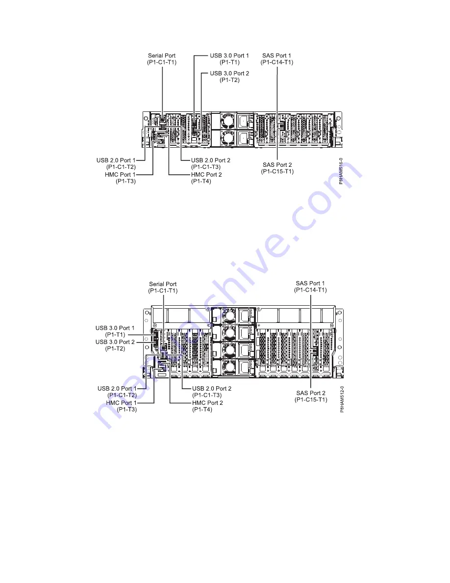
Connector locations for the 8286-41A system

Learn about connector locations for the 8286-41A rack-mounted and stand-alone models.

The 8286-41A server provides cable connector locations via a SAS port for disk drive enclosures.

Figure 26. Connector locations for the expanded function 5148-22L, 8247-21L, 8247-22L, 8284-21A, and 8284-22A
systems

Figure 27. Connector locations for the rack-mounted 8286-41A (expanded function) system

38

Power Systems: Installing the EMX0 PCIe Gen3 I/O expansion drawer

Содержание EMX0 PCIe3

Страница 1: ...Power Systems Installing the EMX0 PCIe Gen3 I O expansion drawer GI11 9914 04 IBM...

Страница 2: ......

Страница 3: ...Power Systems Installing the EMX0 PCIe Gen3 I O expansion drawer GI11 9914 04 IBM...

Страница 4: ...Notices manual G229 9054 and the IBM Environmental Notices and User Guide Z125 5823 This edition applies to IBM Power Systems servers that contain the POWER8 processor and to all associated models Cop...

Страница 5: ...tem by using the HMC 32 Stopping a system by using the HMC Classic or HMC Enhanced interface 32 Stopping a system by using the HMC Enhanced Tech Preview Pre GA or HMC Enhanced interface 33 Stopping an...

Страница 6: ...iv Power Systems Installing the EMX0 PCIe Gen3 I O expansion drawer...

Страница 7: ...tional copies of safety information documentation can be obtained by calling the IBM Hotline at 1 800 300 8751 German safety information Das Produkt ist nicht f r den Einsatz an Bildschirmarbeitspl tz...

Страница 8: ...t 1 Turn off everything unless instructed otherwise 2 For AC power remove the power cords from the outlets 3 For racks with a DC power distribution panel PDP turn off the circuit breakers located in t...

Страница 9: ...mperatures will exceed the manufacturer s recommended ambient temperature for all your rack mounted devices v Do not install a unit in a rack where the air flow is compromised Ensure that air flow is...

Страница 10: ...otential hazards v Verify that the route that you choose can support the weight of the loaded rack cabinet Refer to the documentation that comes with your rack cabinet for the weight of a loaded rack...

Страница 11: ...DANGER Rack mounted devices are not to be used as shelves or work spaces L002 L003 1 2 or 1 2 or 1 2 3 4 or Safety notices ix...

Страница 12: ...equipped with multiple AC power cords or multiple DC power cables To remove all hazardous voltages disconnect all power cords and power cables L003 L007 CAUTION A hot surface nearby L007 L008 x Power...

Страница 13: ...tacle Although shining light into one end and looking into the other end of a disconnected optical fiber to verify the continuity of optic fibers many not injure the eye this procedure is potentially...

Страница 14: ...nging load v Do not use on uneven surface incline or decline major ramps v Do not stack loads v Do not operate while under the influence of drugs or alcohol v Do not support ladder against LIFT TOOL v...

Страница 15: ...ing interfaces only Type 2 or Type 4 ports as described in GR 1089 CORE and require isolation from the exposed OSP cabling The addition of primary protectors is not sufficient protection to connect th...

Страница 16: ...xiv Power Systems Installing the EMX0 PCIe Gen3 I O expansion drawer...

Страница 17: ...EMX0 PCIe3 expansion drawer 3 Determining and marking the location in the rack 4 Attaching the mounting hardware to the rack 5 Installing the EMX0 PCIe3 expansion drawer into the rack Preparing to in...

Страница 18: ...wer is turned on For details see Installing a part by using the HMC http www ibm com support knowledgecenter POWER8 p8haj hmcinstall htm 3 Determine the level of software that you need to support the...

Страница 19: ...If you do not have a rack that is installed install the rack For instructions see Racks and rack features http www ibm com support knowledgecenter POWER8 p8hbf p8hbf_8xx_kickoff htm v Help to lift th...

Страница 20: ...mounting template you can use the template to mark the locations instead of using the manual method that is described in steps 6 on page 6 9 on page 7 To determine where to install the drawer into a...

Страница 21: ...l surface of your hardware to prevent the electrostatic discharge from damaging your hardware v When you use an ESD wrist strap follow all electrical safety procedures An ESD wrist strap is used for s...

Страница 22: ...pencil to mark the top mounting hole of the third EIA unit A from the lowest EIA unit you marked Insert a nut clip at this location c Mark the top mounting hole on the lowest EIA unit B Note Mark the...

Страница 23: ...e that mounting hole C You now have two marks C on the rack with one mounting hole between the marks d Count up three mounting holes from where you placed your last mark and place another mark next to...

Страница 24: ...edure it is suggested that you use two people to attach the rail assembly to the rack Position one person in front of the rack and one person at the back of the rack To install the mounting hardware i...

Страница 25: ...he rack complete the following steps a Extend the right rail and insert the rail pins D into the two lowest mounting holes that are marked on the rack so that the rail is facing upward as shown in Fig...

Страница 26: ...rack 7 Move to the front of the rack and complete the following steps a Use one M5 screw E below the lower rail pin D to secure the left rail to the front of the rack b Use one M5 screw E below the lo...

Страница 27: ...ove it by completing the following steps a If there are M5 securing screws on the cover remove them b Using the two blue touch points on each side of the drawer pull the cover straight out to remove t...

Страница 28: ...e drawer into position over the slide rails and slide the drawer into the rack 6 Install the two M5 securing screws J through the drawer and into the nut clips on the left and right rails See Figure 9...

Страница 29: ...e the bottom of the mounting flanges on the cable management bracket B over the two M5 screws to support the bracket flanges against the rack c Align the bracket so that its mounting flanges B align w...

Страница 30: ...ners B and turn them to disengage them while you lift the cable management bracket A to its raised position 1 b Turn the quarter turn fasteners B to engage and lock the bracket into position P8EGP505...

Страница 31: ...t and turn them to disengage them while moving the cable management bracket A to its lower position 2 See Figure 13 on page 16 b Turn the quarter turn fasteners B to engage and lock the bracket into p...

Страница 32: ...in Figure 14 Note If you have a different scenario the securing screws are optional 13 Continue with Connecting an EMX0 PCIe3 expansion drawer to your system on page 17 Figure 13 Placing the cable man...

Страница 33: ...umber of PCIe3 6 slot fanout modules installed v For instructions about installing a PCIe3 cable adapter or PCIe3 6 slot fanout module when the system power is turned on see Installing a part by using...

Страница 34: ...ach the host system location labels to the expansion drawer cable Note While you are completing these steps refer to Figure 15 on page 19 as a reference a Locate the host system A that you are attachi...

Страница 35: ...label to the connector end of the cable K See Figure 15 Wrap the label with the blank end first so that the location information F is visible g Take the second Px T1 label from the expansion drawer la...

Страница 36: ...carabiner so that the cables clear the PCIe3 6 slot fanout module or modules See Figure 16 c Connect the other ends of the power cables into the power supplies on the EMX0 PCIe3 expansion drawer you a...

Страница 37: ...d retention 18 If the system has a rear door close or replace it 19 Verify that the system or logical partition recognizes the drawer For instructions see Verifying the installed part http www ibm com...

Страница 38: ...arm use the 3 meter cables v If your system and EMX0 PCIe3 expansion drawer are in separate racks use the 10 meter cables v If you have a 9080 MHE 9080 MME 9119 MHE or 9119 MME system and the EMX0 PC...

Страница 39: ...ee Figure 17 9 Attach the EMX0 PCIe3 expansion drawer location labels to the expansion drawer cable Note While you are completing these steps refer to Figure 17 as a reference a Locate the EMX0 PCIe3...

Страница 40: ...pposite connector end near the I O module on the EMX0 PCIe3 expansion drawer c Repeat this step for the other cable in the pair and for other cable pairs 15 To connect the expansion drawer cables to t...

Страница 41: ...to move to the lowest position v For more information about managing cables see Cable management on page 29 and Power cord routing and retention Connecting power cables and powering on the system and...

Страница 42: ...5 If you are using an HMC Classic or HMC Enhanced interface complete the following steps a In the HMC navigation area expand Systems Management and click Servers b Select the check box next to the nam...

Страница 43: ...tion start policy field so that you can restore the setting later in this procedure 4 Set the Partition start policy field to User Initiated Click OK d In the navigation area select System Actions Ope...

Страница 44: ...one of the following options v Power on one or more logical partitions For instructions see Starting the system or logical partition on page 34 Notes If you start a partition while the system is in th...

Страница 45: ...brackets and other features that may be provided for cable management v Install and route the communications cables starting with smallest diameter first and then progressing to the largest diameter...

Страница 46: ...potentially cause system operations to stop functioning Different types of power cord retention are available Some of the most commonly used types of retention include v Cable management arms v Rings...

Страница 47: ...o stop the system or logical partition select the appropriate procedure Stopping a system that is not managed by an HMC You might need to stop the system to complete another task If your system is not...

Страница 48: ...r On Off System The power state of the system is displayed 3 Specify the settings as required and click Save setting and power off Stopping a system by using the HMC You can use the Hardware Managemen...

Страница 49: ...tem name for which you want to deactivate partitions c Select the logical partitions that you want to deactivate d In the content pane click Actions Deactivate e Click OK 2 To power off the system com...

Страница 50: ...power button on the control panel ensure that power is connected to the system unit as follows v All system power cables are connected to a power source v The power LED as shown in the following figur...

Страница 51: ...or your service provider Starting a system by using the ASMI You can use the Advanced System Management Interface ASMI to start a system that is not managed by a Hardware Management Console HMC To sta...

Страница 52: ...Actions View All Actions Power On d Click OK 2 To activate a logical partition complete the following steps a In the navigation area click the Resources icon and then click All Partitions b Click the...

Страница 53: ...about the EMX0 PCIe3 expansion drawer locations see PCIe Gen3 I O expansion drawer locations http www ibm com support knowledgecenter POWER8 p8ecs p8ecs_emx0_loccodes htm Connector locations for POWE...

Страница 54: ...ver provides cable connector locations via a SAS port for disk drive enclosures Figure 26 Connector locations for the expanded function 5148 22L 8247 21L 8247 22L 8284 21A and 8284 22A systems Figure...

Страница 55: ...d models The 8247 42L and 8286 42A expanded function servers provide cable connector locations via a SAS port for disk drive enclosures Figure 28 Connector locations for the stand alone 8286 41A expan...

Страница 56: ...P1 C5 T2 for the EMX0 PCIe3 expansion drawer Connector locations for the 9080 MHE 9080 MME 9119 MHE and 9119 MME systems Learn about connector locations for the 9080 MHE 9080 MME 9119 MHE and 9119 MME...

Страница 57: ...1 C9 P1 C9 T1 P1 C9 T2 P1 C11 P1 T7 P1 C5 P1 C6 P1 C7 P1 C8 P1 C5 C1 P1 C6 C1 P1 C7 C1 P1 C8 C1 P1 C1 P1 C1 C1 P1 C2 P1 C3 P1 C4 P1 C2 C1 P1 C3 C1 P1 C4 C1 P8ECS804 1 Figure 31 Connector locations for...

Страница 58: ...42 Power Systems Installing the EMX0 PCIe Gen3 I O expansion drawer...

Страница 59: ...efore this statement may not apply to you This information could include technical inaccuracies or typographical errors Changes are periodically made to the information herein these changes will be in...

Страница 60: ...in sensitive or critical operations Users should periodically check IBM s support websites for updated information and fixes applicable to the system and related software Homologation statement This p...

Страница 61: ...www ibm com able Privacy policy considerations IBM Software products including software as a service solutions Software Offerings may use cookies or other technologies to collect product usage inform...

Страница 62: ...radio communications Operation of this equipment in a residential area is likely to cause harmful interference in which case the user will be required to correct the interference at his own expense Pr...

Страница 63: ...erence may occur in which case the user may be required to take corrective actions Japan Electronics and Information Technology Industries Association Statement This statement explains the Japan JIS C...

Страница 64: ...to perform practical action Electromagnetic Interference EMI Statement Taiwan The following is a summary of the EMI Taiwan statement above Warning This is a Class A product In a domestic environment...

Страница 65: ...g kann im Wohnbereich Funk St rungen verursachen in diesem Fall kann vom Betreiber verlangt werden angemessene Ma nahmen zu ergreifen und daf r aufzukommen Deutschland Einhaltung des Gesetzes ber die...

Страница 66: ...an outlet on a circuit different from that to which the receiver is connected v Consult an IBM authorized dealer or service representative for help Properly shielded and grounded cables and connector...

Страница 67: ...tion Statement This statement explains the Japan JIS C 61000 3 2 product wattage compliance This statement explains the Japan Electronics and Information Technology Industries Association JEITA statem...

Страница 68: ...ne Zustimmung von IBM ver ndert bzw wenn Erweiterungskomponenten von Fremdherstellern ohne Empfehlung von IBM gesteckt eingebaut werden Deutschland Einhaltung des Gesetzes ber die elektromagnetische V...

Страница 69: ...oprietary notices are preserved You may not make derivative works of these publications or reproduce distribute or display these publications or any portion thereof outside your enterprise without the...

Страница 70: ...54 Power Systems Installing the EMX0 PCIe Gen3 I O expansion drawer...

Страница 71: ......

Страница 72: ...IBM Part Number 01LK530 Printed in USA GI11 9914 04 1P P N 01LK530...

Отзывы: