


v
Reinstall the two upper flex circuit assemblies (see page “Upper flex circuit
assembly” on page 64).
v
Reinstall the two lower flex circuit assemblies (see page “Lower flex circuit
assembly” on page 66).
v
Reinstall the rear ac panel (see “Rear panel” on page 63).
v
Reinstall the LAN module (see “Installing the LAN module” on page 55).
v
Reinstall the KVM module (see “Installing the KVM module” on page 54).
v
Reinstall the I/O switches or switch fillers.
v
Plug each power cord into the input power connections on the rear of the
BladeCenter T unit.
v
Reinstall the power modules at the front of the unit (see “Installing a power
module” on page 45).
15.
Start the system (see “Starting the BladeCenter T unit” on page 16).
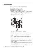
Backplane
Complete the following steps to replace the backplane in your BladeCenter T unit:
Note:
v
Read “Installation guidelines” on page 35.
v
Read the safety notices in “Safety” on page v.
v
Read “Handling static-sensitive devices” on page 37.
1.
Shut down and remove power from the system (see “Shutting down the
BladeCenter T unit” on page 17).
2.
Remove each power cord from the input power connections on the rear of the
BladeCenter T unit.
3.
Remove the power modules from the bays at the front of the BladeCenter T
unit.
Note:
The power modules dock into the docking board on the assembly and
must be removed before you can remove the assembly.
4.
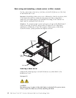
At the rear of the unit, remove all four blowers from both docking
board/blower housing assemblies (see “Removing a blower module” on page
52).
5.
Remove the KVM module from the rear of the system (see “Removing the
KVM module” on page 54).
6.
Remove the LAN module from the rear of the system (see “Removing the
LAN module” on page 55).
7.
Remove all I/O switches and switch fillers from the rear of the unit.
8.
Remove the ac rear panel from the rear of the unit (see “Rear panel” on page
63).
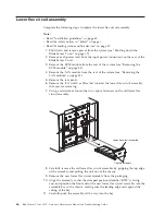
9.
Remove the two upper flex circuit assemblies (see “Upper flex circuit
assembly” on page 64) and the two lower flex circuit assemblies (see “Lower
flex circuit assembly” on page 66).
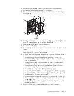
10.
For each docking board/blower housing assembly, loosen the two captive
fasteners located above and below the power inlet receptacles.
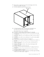
11.
Grasp the left docking board/blower assembly housing by the frame and
carefully pull the housing out from the system chassis.
12.
Grasp the right docking board/blower assembly housing by the frame and
carefully pull the housing out from the system chassis.
70
BladeCenter T Type 8267: Hardware Maintenance Manual and Troubleshooting Guide
Содержание BladeCenter T
Страница 1: ...BladeCenter T Type 8267 Hardware Maintenance Manual and Troubleshooting Guide ...
Страница 2: ......
Страница 3: ...BladeCenter T Type 8267 Hardware Maintenance Manual and Troubleshooting Guide ...
Страница 16: ...xiv BladeCenter T Type 8267 Hardware Maintenance Manual and Troubleshooting Guide ...
Страница 20: ...xviii BladeCenter T Type 8267 Hardware Maintenance Manual and Troubleshooting Guide ...
Страница 52: ...32 BladeCenter T Type 8267 Hardware Maintenance Manual and Troubleshooting Guide ...
Страница 102: ...82 BladeCenter T Type 8267 Hardware Maintenance Manual and Troubleshooting Guide ...
Страница 126: ...106 BladeCenter T Type 8267 Hardware Maintenance Manual and Troubleshooting Guide ...
Страница 134: ...Taiwan Class A compliance statement 114 BladeCenter T Type 8267 Hardware Maintenance Manual and Troubleshooting Guide ...
Страница 138: ...118 BladeCenter T Type 8267 Hardware Maintenance Manual and Troubleshooting Guide ...
Страница 139: ......
Страница 140: ... Part Number 94Y7061 Printed in USA 1P P N 94Y7061 ...