


1.
Install any options that you need, such as hard disk drives or memory, in the
blade server. See the documentation that comes with the blade server for
instructions.
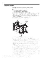
2.
Select the bay for the blade server.
Notes:
a.
If a blade server has a SCSI Storage Expansion Unit or PCI I/O-expansion
Unit installed on it, the blade server and expansion option require an
additional adjacent blade bay.
b.
If you install a blade server or option in bay 5 through 8, you must install
power modules in power-module bays 3 and 4.
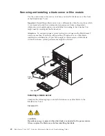
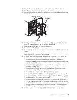
3.
Remove the filler blade from the bay and store in a safe place.
4.
Make sure that the release latches on the blade server are in the open position
(horizontal to the blade server).
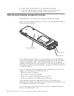
5.
Slide the blade server into the bay until it stops.
6.
Push the release latches on the front of the blade server until they are closed.
7.
Turn on the blade server by pressing the power-control button on the blade
server control panel. See the documentation that comes with the blade server
for more instructions.
8.
Make sure that the power LED on the blade server control panel is lit,
indicating that the blade server is receiving power.
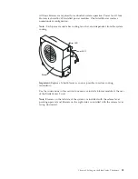
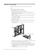
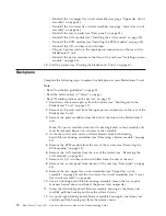
9.
(Optional) Write identifying information on one of the user labels that come
with the blade server; then, place the label on the BladeCenter T unit to the
right of the blade server, as shown in the following illustration.
User
label
CMM
1
CMM
2
Important:
Do not place the label on the blade server or in any way block the
ventilation holes on the blade server.
10.
If you have other modules to install at the front of the unit, do so now.
Otherwise reinstall the bezel assembly on the front of the BladeCenter T unit.
Note:
Reinstall the bezel assembly on the BladeCenter T unit after you have
finished installing the blades. However, if you installed an option such as a
PCI I/O Expansion Unit with PCI adapters that require cables, you will not be
able to install the bezel assembly, which contains an air filter for the
BladeCenter T unit. If you cannot install the bezel assembly, a filter must be
provided on the rack.
Chapter 4. Setting up the BladeCenter T hardware
61
Содержание BladeCenter T
Страница 1: ...BladeCenter T Type 8267 Hardware Maintenance Manual and Troubleshooting Guide ...
Страница 2: ......
Страница 3: ...BladeCenter T Type 8267 Hardware Maintenance Manual and Troubleshooting Guide ...
Страница 16: ...xiv BladeCenter T Type 8267 Hardware Maintenance Manual and Troubleshooting Guide ...
Страница 20: ...xviii BladeCenter T Type 8267 Hardware Maintenance Manual and Troubleshooting Guide ...
Страница 52: ...32 BladeCenter T Type 8267 Hardware Maintenance Manual and Troubleshooting Guide ...
Страница 102: ...82 BladeCenter T Type 8267 Hardware Maintenance Manual and Troubleshooting Guide ...
Страница 126: ...106 BladeCenter T Type 8267 Hardware Maintenance Manual and Troubleshooting Guide ...
Страница 134: ...Taiwan Class A compliance statement 114 BladeCenter T Type 8267 Hardware Maintenance Manual and Troubleshooting Guide ...
Страница 138: ...118 BladeCenter T Type 8267 Hardware Maintenance Manual and Troubleshooting Guide ...
Страница 139: ......
Страница 140: ... Part Number 94Y7061 Printed in USA 1P P N 94Y7061 ...