


v
Orange on a component or an orange label on or near a component indicates
that the component can be hot-swapped, which means that you can remove or
install the component while the BladeCenter Tunit is running. (Orange can also
indicate touch points on hot-swap components.) See the instructions for
removing or installing a specific hot-swap component for any additional
procedures that you might have to perform before you remove or install the
component.
v
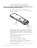
You do not need to disconnect the BladeCenter T unit from power to install or
replace any of the hot-swap modules in the BladeCenter T unit. You need to
shut down the operating system and turn off a hot-swap blade server on the
front of the BladeCenter T unit before removing the blade server, but you do not
need to shut down the BladeCenter T unit itself.
v
For a list of supported options for your server, go to http://www.ibm.com/
supportportal/ .
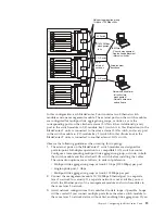
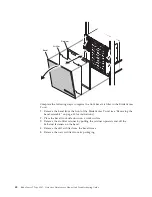
Preparing for system power
The BladeCenter T unit can support two or four power modules.
The BladeCenter T unit does not have a power switch. To start the BladeCenter T
unit, connect one end of a power cord into input power connector 1 and 2 on the
rear of the BladeCenter T unit, and the other end of each power cord into a
220-volt power distribution unit (PDU) that is connected into an appropriate
electrical outlet.
There are four IEC 60320 (C20) power connectors on the rear of the BladeCenter T
unit, marked 1-4 on the rear panel. Power is applied to the respective power
module according to the numbering convention on the rear panel.
v
Power connector 1 supplies power to power module 1
v
Power connector 2 supplies power to power module 2
v
Power connector 3 supplies power to power module 3
v
Power connector 4 supplies power to power module 4
System reliability considerations
To help ensure proper cooling and system reliability, make sure that:
v
Each of the module bays on the front and rear of the BladeCenter T unit has
either a module or filler module installed.
v
Each of the blade bays on the front of the BladeCenter T unit has either a blade
server or filler blade installed.
v
Each of the drive bays in a blade server storage expansion option has either a
hot-swap drive or a filler panel installed.
v
Each of the PCI slots in a blade server PCI I/O expansion option has either a
PCI adapter or a PCI filler bracket installed
v
A removed hot-swap module or drive is replaced within 1 minute of removal.
v
A removed hot-swap blade is replaced within 20 minutes of removal.
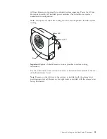
v
A failed blower is replaced as soon as possible, to restore cooling redundancy.
36
BladeCenter T Type 8267: Hardware Maintenance Manual and Troubleshooting Guide
Содержание BladeCenter T
Страница 1: ...BladeCenter T Type 8267 Hardware Maintenance Manual and Troubleshooting Guide ...
Страница 2: ......
Страница 3: ...BladeCenter T Type 8267 Hardware Maintenance Manual and Troubleshooting Guide ...
Страница 16: ...xiv BladeCenter T Type 8267 Hardware Maintenance Manual and Troubleshooting Guide ...
Страница 20: ...xviii BladeCenter T Type 8267 Hardware Maintenance Manual and Troubleshooting Guide ...
Страница 52: ...32 BladeCenter T Type 8267 Hardware Maintenance Manual and Troubleshooting Guide ...
Страница 102: ...82 BladeCenter T Type 8267 Hardware Maintenance Manual and Troubleshooting Guide ...
Страница 126: ...106 BladeCenter T Type 8267 Hardware Maintenance Manual and Troubleshooting Guide ...
Страница 134: ...Taiwan Class A compliance statement 114 BladeCenter T Type 8267 Hardware Maintenance Manual and Troubleshooting Guide ...
Страница 138: ...118 BladeCenter T Type 8267 Hardware Maintenance Manual and Troubleshooting Guide ...
Страница 139: ......
Страница 140: ... Part Number 94Y7061 Printed in USA 1P P N 94Y7061 ...