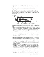


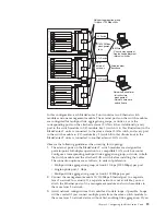


operate together as an aggregate link, or trunk. An aggregate link provides more
bandwidth than a single link to the attached LAN.
Notes:
1.
The attaching LAN switch must have a compatible multiport trunk
configuration.
2.
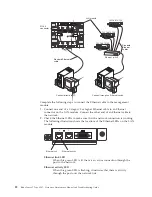
Configure link aggregation before you attach cables between the external ports
and your LAN equipment.
Configure the switch through the user interface on the switch module, which you
can access through the Web interface to the management module (click
I/O
Module Tasks ” Management ” Advanced Management ” Start Telnet/Web
Session in the navigation pane
).
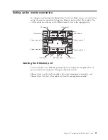
Important:
For a remote management station, such as a management server, to
communicate with the switch modules in the BladeCenter T unit, the management
port of the switch module must be on the same subnet as the management
module.
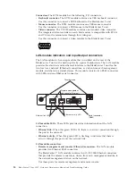
Supporting Ethernet failover
To have the BladeCenter T unit support Ethernet failover on the blade servers, set
up the BladeCenter T unit and blade servers as follows:
1.
Configure the Ethernet controllers in one or more blade servers for failover (see
the blade server documentation and the operating-system documentation for
information). When failover occurs on a blade server, the secondary Ethernet
controller takes over network communication, using the I/O module associated
with that controller.
2.
Install a switch module or a pass-thru module that is connected to external
Ethernet switches in both I/O-module bays 1 and 2.
3.
Configure the Ethernet switch modules and your network infrastructure so that
they can direct traffic to the same destinations.
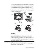
Configuring the Ethernet controllers in the blade servers
Note:
The BladeCenter T unit does not include an Ethernet switch module; this is
an optional feature that must be purchased separately. An Ethernet switch module
or a pass-thru module is connected to an external Ethernet switch must be
installed in the BladeCenter T unit in I/O-module bay 1 or 2, or both, before the
integrated Ethernet controllers on each blade server system board can be used.
The Ethernet controllers are integrated on each blade server system board. The
Ethernet controllers provide 1-Gbps full-duplex capability only, which enables
simultaneous transmission and reception of data to the external ports on the
Ethernet switches. You do not need to set any jumpers or configure the controller
for the blade server operating system. However, you must install a device driver
on the blade server to enable the blade server operating system to address the
Ethernet controller. For blade server device drivers and information about
configuring the Ethernet controllers, go to http://www.ibm.com/supportportal/ .
Chapter 2. Configuring the BladeCenter T unit
27
Содержание BladeCenter T
Страница 1: ...BladeCenter T Type 8267 Hardware Maintenance Manual and Troubleshooting Guide ...
Страница 2: ......
Страница 3: ...BladeCenter T Type 8267 Hardware Maintenance Manual and Troubleshooting Guide ...
Страница 16: ...xiv BladeCenter T Type 8267 Hardware Maintenance Manual and Troubleshooting Guide ...
Страница 20: ...xviii BladeCenter T Type 8267 Hardware Maintenance Manual and Troubleshooting Guide ...
Страница 52: ...32 BladeCenter T Type 8267 Hardware Maintenance Manual and Troubleshooting Guide ...
Страница 102: ...82 BladeCenter T Type 8267 Hardware Maintenance Manual and Troubleshooting Guide ...
Страница 126: ...106 BladeCenter T Type 8267 Hardware Maintenance Manual and Troubleshooting Guide ...
Страница 134: ...Taiwan Class A compliance statement 114 BladeCenter T Type 8267 Hardware Maintenance Manual and Troubleshooting Guide ...
Страница 138: ...118 BladeCenter T Type 8267 Hardware Maintenance Manual and Troubleshooting Guide ...
Страница 139: ......
Страница 140: ... Part Number 94Y7061 Printed in USA 1P P N 94Y7061 ...