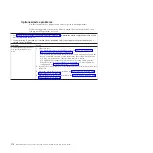
Light path diagnostics LEDs
Use this information to diagnose and resolve possible errors displayed by the light
path diagnostic LEDs.
The following table describes the LEDs on the light path diagnostics panels, on the
system board, and on the optional expansion unit and suggested actions to correct
the detected problems.
v
Follow the suggested actions in the order in which they are listed in the Action column until the problem is
solved.
v
See Chapter 4, “Parts listing, Types 7871 and 1949,” on page 41 to determine which components are CRUs and
which components are FRUs.
v
If an action step is preceded by “(Trained service technician only),” that step must be performed only by a
trained service technician.
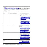
Lit light path
diagnostics LED
Description
Action
None
An error has occurred and cannot be isolated,
or the service processor has failed.
1.
Make sure that the light path diagnostics
LED is lit, to ensure that there is enough
power in the blade server to light the rest
of the LEDs. See “Viewing the light path
diagnostics LEDs” on page 181.
2.
Check the BMC log for information about
an error that is not represented by a light
path diagnostics LED. See “Using the
Setup utility” on page 20.
Battery error
The system battery is not installed or is not
working.
1.
Reseat the battery. See “Removing the
battery” on page 71 and “Installing the
battery” on page 72.
2.
Replace the battery. See “Removing the
battery” on page 71 and “Installing the
battery” on page 72.
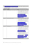
DIMM x error
A memory error occurred.
Look for system-event and IMM/AMM logs
related to memory and resolve those events
(see “IMM error messages” on page 101 and
“POST error codes” on page 144
LP1
v
LP1 LED on system board: system-board
assembly light path diagnostic LEDs have
power.
v
LP1 LED on optional expansion unit: check
light path LEDs on the system board.
Check for error LEDs that are lit on the
system-board assembly. See “Viewing the light
path diagnostics LEDs” on page 181.
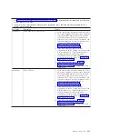
LP2
(optional
expansion unit
only)
Light path diagnostic LEDs on the optional
expansion unit have power.
Check for error LEDs that are lit on the
optional expansion unit. See “Viewing the
light path diagnostics LEDs” on page 181.
Chapter 6. Diagnostics
183
Содержание BladeCenter HS22V 7871
Страница 1: ...BladeCenter HS22V Type 7871 and 1949 Problem Determination and Service Guide...
Страница 2: ......
Страница 3: ...BladeCenter HS22V Type 7871 and 1949 Problem Determination and Service Guide...
Страница 16: ...xiv BladeCenter HS22V Type 7871 and 1949 Problem Determination and Service Guide...
Страница 20: ...4 BladeCenter HS22V Type 7871 and 1949 Problem Determination and Service Guide...
Страница 34: ...18 BladeCenter HS22V Type 7871 and 1949 Problem Determination and Service Guide...
Страница 64: ...48 BladeCenter HS22V Type 7871 and 1949 Problem Determination and Service Guide...
Страница 112: ...96 BladeCenter HS22V Type 7871 and 1949 Problem Determination and Service Guide...
Страница 240: ...224 BladeCenter HS22V Type 7871 and 1949 Problem Determination and Service Guide...
Страница 244: ...228 BladeCenter HS22V Type 7871 and 1949 Problem Determination and Service Guide...
Страница 252: ...236 BladeCenter HS22V Type 7871 and 1949 Problem Determination and Service Guide...
Страница 257: ......
Страница 258: ...Part Number 00Y8038 Printed in USA 1P P N 00Y8038...


