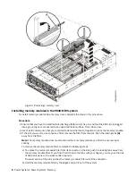


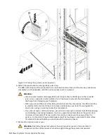
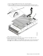
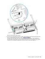

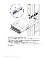


Figure 15. Removing a memory riser
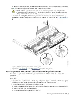
11. Place the memory riser on an electrostatic discharge (ESD) mat.
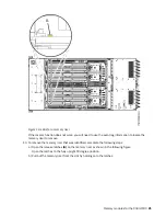
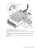
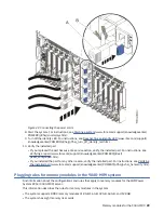
Removing a memory module from the 9040-MR9 system
To remove a memory module from the system, complete the steps in this procedure.
Procedure
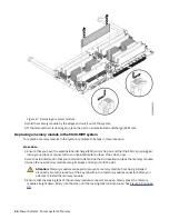
1. Ensure that you have the electrostatic discharge (ESD) wrist strap on and that the ESD clip is plugged
into a ground jack or connected to an unpainted metal surface. If not, do so now.
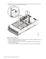
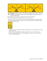
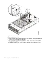
2. To determine which memory module is faulty in the memory riser, press the locator button (A) on the
memory riser. The green LED at (B) indicates whether the memory riser indicators have enough power
to light the memory module indicators. The yellow LED at (C) indicates an issue with the memory riser.
The LED for the faulty memory module LEDs are at (D).
If the locator function does not work, you will need to use the event log information to locate the
memory module to replace.
22 Power Systems: Power Systems: Memory
Содержание 9040-MR9
Страница 1: ...Power Systems Memory modules for the 9040 MR9 IBM ...
Страница 4: ...iv ...
Страница 14: ...xiv Power Systems Power Systems Memory ...
Страница 17: ...Figure 1 Removing the power cords L003 or or Memory modules for the 9040 MR9 3 ...
Страница 30: ...or or or or 16 Power Systems Power Systems Memory ...
Страница 46: ...Figure 23 Removing the power cords L003 or or 32 Power Systems Power Systems Memory ...
Страница 59: ...Figure 32 Removing the power cords L003 or or Memory riser for the 9040 MR9 45 ...
Страница 70: ...Figure 40 Removing the power cords L003 or or 56 Power Systems Power Systems Memory ...
Страница 86: ...or or or or 72 Power Systems Power Systems Memory ...
Страница 105: ......
Страница 106: ...IBM ...