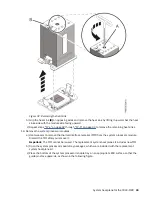


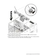


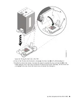


Figure 48. Reconnecting the cable to its connector on the power midplane
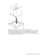
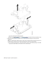
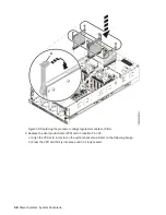
4. Remove the socket dust covers from the system processor module sockets on the new system
backplane.
a) Grasp the latches on both sides of the socket dust cover and squeeze them inwards until the
latches release from the pins on the system backplane.
b) Lift the socket dust cover straight up as shown in the following figure. Set the dust cover aside.
System backplane for the 9040-MR9 47
Содержание 9040-MR9
Страница 1: ...Power Systems System backplane for the 9040 MR9 IBM...
Страница 4: ...iv...
Страница 14: ...xiv Power Systems System backplane...
Страница 17: ...or or or or System backplane for the 9040 MR9 3...
Страница 98: ...84 Power Systems System backplane...
Страница 109: ......
Страница 110: ...IBM...