background image

Power-on


LED


When


this


LED


is


lit,


it


indicates


that


the


server


is


turned


on.


When


this


LED


is


off,


it


indicates


that


ac


power


is


not


present,


or


the


power


supply


or


the


LED


itself


has


failed.


Note:


If


this


LED


is


off,


it


does


not


mean


that


there


is


no


electrical


power


in


the


server.


The


LED


might


be


burned


out.


To


remove


all


electrical


power


from


the


server,


you


must


disconnect


the


power


cord


from


the


electrical


outlet.

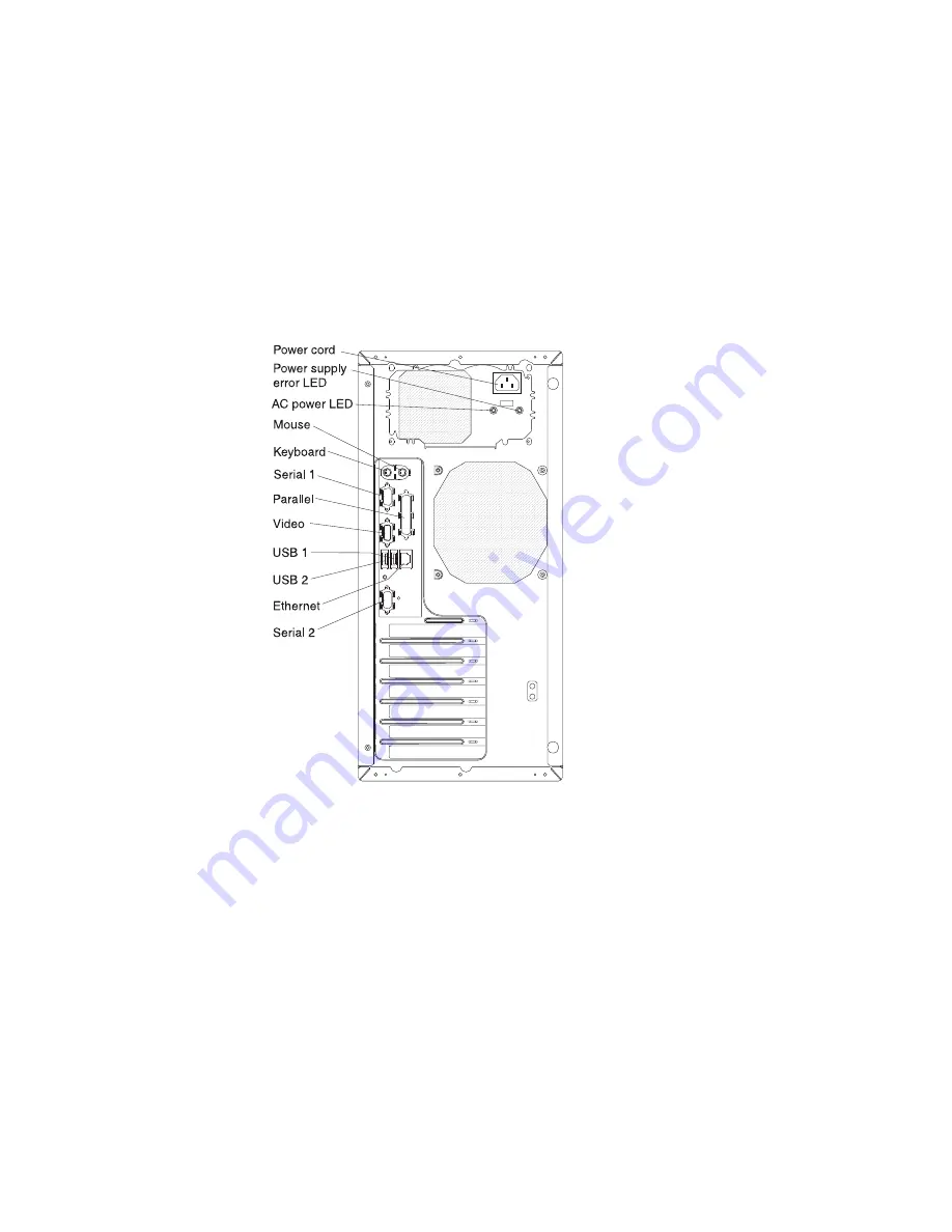
Rear


view


The


following


illustration


shows


the


connectors


on


the


rear


of


the


server.


Power-cord


connector


Connect


the


power


cord


to


this


connector.


Power


supply


error


LED


When


this


amber


LED


is


lit,


it


indicates


that


a


power


supply


error


has


occurred.


AC


power


LED


When


this


green


LED


is


lit,


it


indicates


that


the


server


is


connected


to


an


ac


power


source.


Mouse


connector


Connect


a


mouse


or


other


PS/2

®


device


to


this


connector.


Keyboard


connector


Connect


a


PS/2


keyboard


to


this


connector.


Serial


1


connector


Connect


a


9-pin


serial


device


to


this


connector.


Chapter


1.


The


xSeries


100


Type


8486


server


9

Содержание 8486 - eServer xSeries 100

Страница 1: ...xSeries 100 Type 8486 User s Guide ERserver...

Страница 2: ......

Страница 3: ...xSeries 100 Type 8486 User s Guide ERserver...

Страница 4: ...and the Warranty and Support Information document on the IBM xSeries Documentation CD First Edition October 2005 Copyright International Business Machines Corporation 2005 All rights reserved US Gover...

Страница 5: ...emoving the side cover 18 Removing the bezel 19 Installing a memory module 20 Installing a drive 23 Installing a removable media drive in bay 2 or 3 24 Installing a SATA hard disk drive in bay 4 or 5...

Страница 6: ...Broadcom NetXtreme Gigabit Ethernet Utility program 45 Configuring the Broadcom NetXtreme Gigabit Ethernet controller 45 Updating IBM Director 46 Appendix Notices 47 Edition notice 47 Trademarks 48 I...

Страница 7: ...alleert eerst de veiligheidsvoorschriften Ennen kuin asennat t m n tuotteen lue turvaohjeet kohdasta Safety Information Avant d installer ce produit lisez les consignes de s curit Vor der Installation...

Страница 8: ...t or disconnect signal cables v Never turn on any equipment when there is evidence of fire water or structural damage v Disconnect the attached power cords telecommunications systems networks and mode...

Страница 9: ...es or regulations Statement 3 CAUTION When laser products such as CD ROMs DVD drives fiber optic devices or transmitters are installed note the following v Do not remove the covers Removing the covers...

Страница 10: ...utton on the device and the power switch on the power supply do not turn off the electrical current supplied to the device The device also might have more than one power cord To remove all electrical...

Страница 11: ...ect a problem with one of these parts contact a service technician Statement 12 CAUTION The following label indicates a hot surface nearby Statement 13 DANGER Overloading a branch circuit is potential...

Страница 12: ...o un causante de cancer y de defectos cong nitos adem s de otros riesgos reproductivos L vese las manos despu s de usar el producto Important All caution and danger statements in this documentation be...

Страница 13: ...or you to customize the system hardware to meet your needs today and provide flexible expansion capabilities for the future The server comes with a limited warranty For information about the terms of...

Страница 14: ...ation document v Problem Determination and Service Guide This document is in PDF on the IBM xSeries Documentation CD It contains information to help you solve problems yourself and it contains informa...

Страница 15: ...might help you avoid inconvenient or problem situations v Attention These notices indicate potential damage to programs devices or data An attention notice is placed just before the instruction or sit...

Страница 16: ...5721 10 100 1000 Ethernet controller on the system board with RJ 45 Ethernet port v Two serial ports v One parallel port v Two port Serial ATA controller v Four Universal Serial Bus USB v2 0 ports tw...

Страница 17: ...ware options and provides the correct configuration programs and device drivers For more information about the ServerGuide Setup and Installation CD see Using the ServerGuide Setup and Installation CD...

Страница 18: ...onitoring for fan power temperature and voltage v CD based diagnostic programs v Cooling fans with speed sensing capability v Customer support center that is available 24 hours a day 7 days a week1 v...

Страница 19: ...rs v Support for systems management industry standards v Integration into leading workgroup and enterprise systems management environments v Ease of use training and setup IBM Director also provides a...

Страница 20: ...hen this LED is lit it indicates that the CD or DVD drive is in use USB connectors Connect a USB device to these connectors System error LED When this amber LED is lit it indicates that a system error...

Страница 21: ...l outlet Rear view The following illustration shows the connectors on the rear of the server Power cord connector Connect the power cord to this connector Power supply error LED When this amber LED is...

Страница 22: ...e requests to turn on the server When the Power on LED is flashing it indicates that there is power but the server is not turned on Turning on the server Approximately 20 seconds after the server is c...

Страница 23: ...device ensure that all power cords are disconnected from the power source 1 2 The server can be turned off in any of the following ways v You can turn off the server from the operating system if your...

Страница 24: ...12 xSeries 100 Type 8486 User s Guide...

Страница 25: ...ices in the server Server components The following illustration shows the major components in the server The illustrations in this document might differ slightly from your hardware Cover System board...

Страница 26: ...wer Diskette drive optional Front information panel Battery Microprocessor Front USB System fan 2 System board switches and jumpers The following illustration shows the switches and jumpers on the sys...

Страница 27: ...System board LEDs The following illustration shows the LEDs on the system board System fan 3 error LED2 System fan 1 error LED3 System fan 2 error LED13 Standby power LED1 DIMM 1 error LED17 DIMM 2 er...

Страница 28: ...he area where you are working Place removed covers and other parts in a safe place v If you must start the server while the cover is removed make sure that no one is near the server and that no tools...

Страница 29: ...time more than 30 minutes with the server cover removed might damage server components v You have followed the cabling instructions that come with optional adapters v You have replaced a failed fan a...

Страница 30: ...n its side 4 Remove the two thumbscrews from the rear of the server that secure the cover to the chassis Slide the cover slightly toward the rear of the chassis and lift it off the server and set it a...

Страница 31: ...the side cover on page 18 2 From inside the server locate the two bezel release tabs at the bottom of the bezel Bezel release tabs 3 Press up slightly on both bezel release tabs while pulling the bott...

Страница 32: ...ctor If the server has one DIMM installed when you install an additional DIMM it must be installed in the DIMM 3 connector and it must be the same size speed type and technology as the DIMM in the DIM...

Страница 33: ...the DIMMs in the sequence shown in the following table DIMM 4 DIMM 3 DIMM 2 DIMM 1 DIMM 1 error LED DIMM 2 error LED DIMM 3 error LED DIMM 4 error LED Memory installation sequence DIMMs Slots 1 DIMM 1...

Страница 34: ...e connector by aligning the edges of the DIMM with the slots at the ends of the DIMM connector Firmly press the DIMM straight down into the connector by applying pressure on both ends of the DIMM simu...

Страница 35: ...onsider when installing removable media and hard disk drives v Read the documentation that comes with the drive and make sure that you have all the cables and other equipment specified in the document...

Страница 36: ...and filler panel from the bay the PCI or PCI Express adapter slot cover in the event you later remove the option v For a complete list of supported options for the server see http www ibm com support...

Страница 37: ...from the bezel then pry the EMC shield away from the server Store the filler panel and EMC shield in a safe place Release tab Drive retainer clip EMC shield Filler panel Note If you are installing a d...

Страница 38: ...static protective surface 7 Set any jumpers or switches on the drive according to the documentation that comes with the drive 8 Remove the drive retainer clip located on the side of the drive cage fo...

Страница 39: ...ote Each Serial ATA drive comes with a cable If you install an additional Serial ATA drive you will need an additional cable If you install the optional ServeRAID 7t S ATA controller all SATA drives m...

Страница 40: ...facing you 8 Gently slide the drive assembly into the drive bay as far as it will go 9 Attach the hard disk drive to the drive cage with the four screws 10 Connect one end of the signal cable into the...

Страница 41: ...gnal cables are typically flat cables also called ribbon cables that connect parallel IDE Serial ATA SCSI and diskette drives to the system board Two or three types of signal cables come with the serv...

Страница 42: ...have not changed the default startup sequence PCI Express x8 slot PCI Express x1 slot system board integrated drive electronics IDE or SCSI devices and then PCI slots 3 and 4 v For a list of supporte...

Страница 43: ...correctly seated in the expansion slot before you turn on the server Incomplete installation of an adapter might damage the system board or the adapter Expansion slot cover 8 Reinstall the screw that...

Страница 44: ...ditional information about SCSI adapters Note An optional SCSI adapter or cable option is required to connect external SCSI devices To cable an optional SCSI adapter complete the following steps 1 Ins...

Страница 45: ...ion lock or padlock To install a rope clip complete the following steps 1 Remove the side cover See Removing the side cover on page 18 2 Use a screwdriver to remove the two metal knockouts 3 Insert th...

Страница 46: ...ration Setup Utility program Follow the instructions in this section Installing the bezel To replace the bezel complete the following steps 1 Insert the two alignment tabs at the top of the bezel into...

Страница 47: ...r components are installed and seated correctly and that you have not left loose tools or parts inside the server 2 Align the cover over the server with the rear of the cover slightly hanging off the...

Страница 48: ...ceive a message that the configuration has changed The Configuration Setup Utility program starts automatically so that you can save the new configuration settings See Chapter 3 Configuring the server...

Страница 49: ...network as a startable device and you can customize where the network startup option appears in your startup sequence Enable the Broadcom NetXtreme Gigabit Ethernet Utility from the Configuration Set...

Страница 50: ...ect this choice to view the processor information including the type speed and cache size of the microprocessor v System Information Select this choice to view information about the server When you ma...

Страница 51: ...Select this choice to set passwords For more information about passwords see Passwords on page 41 You can also enable the chassis intrusion detector to alert you each time the server cover is removed...

Страница 52: ...t The server might malfunction if these options are incorrectly configured Follow the instructions on the screen carefully This choice is on the full Configuration Setup Utility menu only PCI Bus Cont...

Страница 53: ...guration Setup Utility menu the system administrator can give the user authority to set change and delete the power on password A user who types the power on password has access to only the limited Co...

Страница 54: ...eps 1 Review the safety information that begins on page v and Handling static sensitive devices on page 17 2 Turn off the server and all attached devices 3 Disconnect the power cord 4 Remove the side...

Страница 55: ...test ServerGuide Setup and Installation CD go to the ServerGuide fulfillment Web site at http www ibm com pc coupon The ServerGuide program has the following features v An easy to use interface v Disk...

Страница 56: ...ng system It provides the device drivers that are required for your hardware and for the operating system that you are installing This section describes a typical ServerGuide operating system installa...

Страница 57: ...you can customize where the network startup option appears in the startup sequence Enable and disable the Broadcom NetXtreme Gigabit Ethernet Utility from the Configuration Setup Utility program To en...

Страница 58: ...t is described in this document 1 Check for the latest version of IBM Director a Go to http www ibm com eserver xseries systems_management xseries_sm dwnl html b Follow the instructions on the Web pag...

Страница 59: ...Y OF ANY KIND EITHER EXPRESS OR IMPLIED INCLUDING BUT NOT LIMITED TO THE IMPLIED WARRANTIES OF NON INFRINGEMENT MERCHANTABILITY OR FITNESS FOR A PARTICULAR PURPOSE Some states do not allow disclaimer...

Страница 60: ...dows and Windows NT are trademarks of Microsoft Corporation in the United States other countries or both UNIX is a registered trademark of The Open Group in the United States and other countries Java...

Страница 61: ...or a particular purpose These products are offered and warranted solely by third parties IBM makes no representations or warranties with respect to non IBM products Support if any for the non IBM prod...

Страница 62: ...op enne et la Norv ge L etiquette du syst me respecte la Directive europ enne 2002 96 EC en mati re de D chets des Equipements Electriques et Electroniques DEEE qui d termine les dispositions de retou...

Страница 63: ...ntrols 8 controls and indicators 8 cooling 4 cover replacing 35 D danger statements 3 data rate Ethernet 45 device driver update 7 DIMM connector installing memory 21 locations 21 DIMM retaining clips...

Страница 64: ...2 forgotten power on 41 password continued lost of forgotten 42 setting 39 using 41 passwords resetting 42 PCI configuration 40 PCI expansion slots 4 power control button 8 power supply specifications...

Страница 65: ...ons 4 systems management 7 T tape drive installing 23 temperature 4 trademarks 48 U update device drivers and firmware 7 using Boot Menu program 45 IBM Configuration Setup Utility program 37 passwords...

Страница 66: ...54 xSeries 100 Type 8486 User s Guide...

Страница 67: ......

Страница 68: ...Part Number 31R2069 Printed in USA 1P P N 31R2069...

Отзывы: