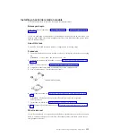
approximately 5 mm of the edge of the microprocessor. This is to ensure
uniform distribution of the grease.
Note:
0.01 mL is one tick mark on the syringe. If the grease is properly applied,
approximately half (0.22 mL) of the grease will remain in the syringe.
6.
Install the heat sink onto the microprocessor as described in “Installing a
microprocessor and heat sink” on page 319.
Removing the microprocessor 2 expansion board
Use this information to remove the microprocessor 2 expansion board.
Before you begin
Read the safety information in “Safety” on page vii and “Installation guidelines”
on page 34.
If you are replacing a component or installing an optional device in the server, you
need to turn off the server and peripheral devices, and disconnect the power cords
and all external cables.
About this task
To remove the microprocessor 2 expansion board, complete the following steps.
Procedure
1.
Carefully turn the server on its side so that it is lying flat, with the cover facing
up.
Attention:
Do not allow the server to fall over.
2.
Unlock and remove the left-side cover (see “Removing the left-side cover” on
page 39).
3.
Remove the air baffle (see “Removing the air baffle” on page 210).
4.
Remove the fan cage assembly (see “Removing the fan cage assembly” on page
304).
5.
Note where the cables are connected to the microprocessor 2 expansion board;
then, disconnect them.
Attention:
Disengage all latches, release tabs or locks on cable connectors
when you disconnect all cables from the system board (see “Internal cable
routing and connectors” on page 186). Failing to release them before removing
the cables will damage the cable sockets on the microprocessor 2 expansion
board. The cable sockets on the microprocessor 2 expansion board are fragile.
Any damage to the cable sockets may require replacing the microprocessor 2
expansion board.
6.
Remove any of the following components that are installed on the
microprocessor 2 expansion board and put them in a safe, static-protective
place:
v
Adapters (see “Removing an adapter” on page 238)
v
DIMMs (see “Removing a memory module” on page 293)
326
System x3500 M4 Type 7383: Installation and Service Guide
Содержание 7383
Страница 1: ...System x3500 M4 Type 7383 Installation and Service Guide ...
Страница 2: ......
Страница 3: ...System x3500 M4 Type 7383 Installation and Service Guide ...
Страница 8: ...vi System x3500 M4 Type 7383 Installation and Service Guide ...
Страница 42: ...24 System x3500 M4 Type 7383 Installation and Service Guide ...
Страница 65: ...Figure 19 Server with sixteen 2 5 inch hard disk drives Chapter 2 Installing optional devices 47 ...
Страница 200: ...182 System x3500 M4 Type 7383 Installation and Service Guide ...
Страница 235: ...Figure 53 Server with eight 2 5 inch hard disk drives Chapter 6 Removing and replacing components 217 ...
Страница 236: ...Figure 54 Server with sixteen 2 5 inch hard disk drives 218 System x3500 M4 Type 7383 Installation and Service Guide ...
Страница 237: ...Figure 55 Server with twenty four 2 5 inch hard disk drives Chapter 6 Removing and replacing components 219 ...
Страница 360: ...342 System x3500 M4 Type 7383 Installation and Service Guide ...
Страница 416: ...398 System x3500 M4 Type 7383 Installation and Service Guide ...
Страница 470: ...452 System x3500 M4 Type 7383 Installation and Service Guide ...
Страница 479: ...Taiwan Class A compliance statement Notices 461 ...
Страница 480: ...462 System x3500 M4 Type 7383 Installation and Service Guide ...
Страница 487: ......
Страница 488: ... Part Number 46W8192 Printed in USA 1P P N 46W8192 ...


