14. Thread down the threaded rod until the tip of the rod is approximately 1 inch inside the turnbuckle.
15. Insert the nuts and hand-tighten the nuts.
16. Repeat the previous three steps so that all assemblies are completely installed, as shown in the
previous illustration.
17. Tighten all the nuts to 40 ft-pounds.
The frame is now secured.
Considerations for Multiple System Installations
In a multi-frame installation, it is possible that a floor tile with cable cutouts (refer to “Cutting and
Placement of Floor Panels” on page 105) will bear two concentrated static loads up to 567 kg (1250 lbs)
per caster/leveler. Thus, the total concentrated load can be as high as 1134 kg (2500 lbs). Contact the
floor tile manufacturer or consult a structural engineer to ensure that the raised floor assembly can support
this load.
When you are integrating an
Eserver
pSeries 655 into an existing multiple-system environment, or when
adding additional systems to an installed
Eserver
pSeries 655, consider the following factors:
v
Minimum aisle width
For multiple rows of systems containing one or more
Eserver
pSeries 655, the minimum aisle width in
the front of the system is 1194 mm (47 in.) and 838 mm (33 in.) in the rear of the system to allow room
to perform service operations. The minimum aisle width is in addition to the front and rear service
clearances of 1143 mm (45 in.) and 914 mm (36 in.) respectively. Service clearances are measured
from the edges of the frame (with doors open) to the nearest obstacle.
v
Thermal interactions
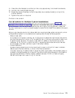
Systems should be faced front-to-front and rear-to-rear to create
″
cool
″
and
″
hot
″
aisles to maintain
effective system thermal conditions, as shown in the following illustration.
Cool aisles need to be of sufficient width to support the airflow requirements of the installed systems as
indicated in Cooling Requirements on Page 90. The airflow per tile will be dependent on the underfloor
pressure and perforations in the tile. A typical underfloor pressure of 0.025 in. of water will supply
300-400 cfm through a 25% open 2 ft. by 2 ft. floor tile.
Chapter 2. Physical Characteristics of Systems
115
Содержание 7012 397
Страница 1: ...RS 6000 and Eserver pSeries Site and Hardware Planning Information SA38 0508 20...
Страница 2: ......
Страница 3: ...RS 6000 and Eserver pSeries Site and Hardware Planning Information SA38 0508 20...
Страница 11: ...Appendix Notices 385 Index 387 Contents ix...
Страница 12: ...x Site and Hardware Planning Information...
Страница 16: ...xiv Site and Hardware Planning Information...
Страница 18: ...xvi Site and Hardware Planning Information...
Страница 26: ...8 Site and Hardware Planning Information...
Страница 238: ...220 Site and Hardware Planning Information...
Страница 246: ...228 Site and Hardware Planning Information...
Страница 284: ...266 Site and Hardware Planning Information...
Страница 296: ...278 Site and Hardware Planning Information...
Страница 366: ...348 Site and Hardware Planning Information...
Страница 372: ...Async Adapter Cable Planning Chart 354 Site and Hardware Planning Information...
Страница 374: ...128 Port Async Controller Cable Planning Chart Controller Line Interface 356 Site and Hardware Planning Information...
Страница 377: ...Standard I O Cable Planning Chart Chapter 12 Cable Planning 359...
Страница 380: ...Cable Planning Chart Other Adapters 362 Site and Hardware Planning Information...
Страница 382: ...7318 Serial Communications Network Server Cable Planning Chart 364 Site and Hardware Planning Information...
Страница 384: ...366 Site and Hardware Planning Information...
Страница 402: ...384 Site and Hardware Planning Information...
Страница 404: ...386 Site and Hardware Planning Information...
Страница 413: ......
Страница 414: ...Printed in USA SA38 0508 20...
Страница 415: ...Spine information RS 6000 and Eserver pSeries Site and Hardware Planning Information...


