


v
The
right
column
is
used
to
determine
the
IOP
to
which
an
IOA
is
assigned.
v
The
first
position
in
the
list
must
be
an
IOP.
The
remaining
positions
may
be
IOPs
or
IOAs.
IOAs
are
assigned
to
the
first
IOP
located
to
their
left
in
the
list.
Although
IOAs
can
be
manually
reassigned
using
SST/DST,
the
IOA
assignments
return
to
the
default
order
after
each
IPL.
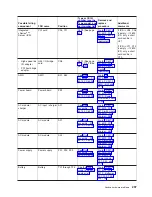
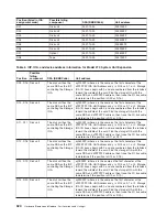
Table
2.
Identify
the
IOP
to
which
IOAs
are
assigned
Multi-adapter
bridge
domain
/
PCI
bridge
set
IOA
assignment
rules
C01
-
C04
C01,
C02,
C03,
C04
C05
-
C09
C05,
C06,
C07,
C08,
C09
C11
-
C15
C11,
C12,
C13,
C14,
C15
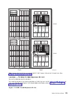
Locations
—
FC
5094
Expansion
I/O
Tower
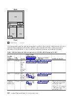
For
use
by
authorized
service
providers.
The
following
diagram
shows
FRU
layout
in
the
FC
5094
Expansion
I/O
Tower.
Use
it
with
the
tables
below.
If
you
need
address
information,
refer
to
Figure
1.
FC
5094
Expansion
I/O
Tower
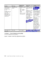
Note:
Do
not
install
power
supplies
P00
and
P01
AC
jumper
cables
on
the
same
AC
module.
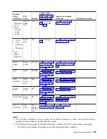
The
following
table
gives
the
components
available
for
callout
on
the
FC
5094,
FC
5294,
and
FC
8094
expansion
I/O
units.
It
matches
those
components
with
the
FRU
containing
the
the
component.
The
other
columns
give
location
information,
CCIN
information,
a
link
to
a
remove
and
replace
procedure,
and
additional
comments.
Table
1.
FRU
locations
and
failing
components
for
FC
5094
Expansion
I/O
Tower
Analyze
hardware
problems
309
Содержание 270
Страница 2: ......
Страница 12: ...x Hardware Remove and Replace Part Locations and Listings...
Страница 279: ...Figure 3 CCIN 2881 with pluggable DIMM Analyze hardware problems 267...
Страница 281: ...Figure 6 Models 830 SB2 with FC 9074 HSL and SPCN locations Analyze hardware problems 269...
Страница 283: ...Figure 1b Model 840 SB3 processor tower dual line cord Analyze hardware problems 271...
Страница 294: ...01 gif port and LED locations 282 Hardware Remove and Replace Part Locations and Listings...
Страница 295: ...s src rzaq4519 gif locations Analyze hardware problems 283...
Страница 318: ...Figure 2 FC 5088 FC 0588 Expansion I O Unit top view 306 Hardware Remove and Replace Part Locations and Listings...
Страница 415: ...Table 2 Final assembly rear Models 830 and SB2 with FC 9074 continued Analyze hardware problems 403...
Страница 422: ...Table 1 Cover assembly Models 840 and SB3 processor tower 410 Hardware Remove and Replace Part Locations and Listings...
Страница 483: ...Table 1 Cover assembly FC 5095 Expansion I O Tower Analyze hardware problems 471...
Страница 505: ...Table 15 Model 830 SB2 System Unit with FC 9074 Power cables single line cord Analyze hardware problems 493...
Страница 511: ...Table 19 Model 840 SB3 Processor Tower Power cables single line cord Analyze hardware problems 499...
Страница 513: ...Table 21 Model 840 and Model SB3 9079 Base I O Tower Power cables dual line cord Analyze hardware problems 501...
Страница 519: ...Figure 15 Models 870 and 890 Primary I O to CEC interconnection part 1 Analyze hardware problems 507...
Страница 614: ...602 Hardware Remove and Replace Part Locations and Listings...
Страница 618: ...606 Hardware Remove and Replace Part Locations and Listings...
Страница 621: ......
Страница 622: ...Printed in USA SY44 5917 02...


