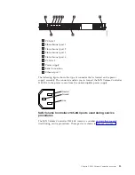
Chapter
4.
Using
the
2145
UPS-1U
The
2145
uninterruptible
power
supply-1U
(2145
UPS-1U)
provides
a
SAN
Volume
Controller
node
with
a
secondary
power
source
if
you
lose
power
from
your
primary
power
source
due
to
power
failures,
power
sags,
power
surges,
or
line
noise.
Unlike
the
traditional
UPS
that
enables
continued
operation
of
the
devices
that
they
supply
when
power
is
lost,
these
UPS
units
are
used
exclusively
to
maintain
data
that
is
held
in
the
SAN
Volume
Controller
dynamic
random
access
memory
(DRAM)
in
the
event
of
an
unexpected
loss
of
external
power.
Data
is
saved
to
the
internal
disk
of
the
SAN
Volume
Controller
node.
The
UPS
units
are
required
to
power
the
SAN
Volume
Controller
nodes
even
if
the
input
power
source
is
considered
uninterruptible.
The
SAN
Volume
Controller
2145-8G4,
SAN
Volume
Controller
2145-8F4,
and
SAN
Volume
Controller
2145-8F2
nodes
can
operate
only
with
the
2145
UPS-1U.
The
SAN
Volume
Controller
2145-4F2
node
can
operate
with
either
the
2145
UPS
or
the
2145
UPS-1U.
Note:
The
UPS
maintains
continuous
SAN
Volume
Controller-specific
communications
with
its
attached
SAN
Volume
Controller
nodes.
A
SAN
Volume
Controller
node
cannot
operate
without
the
UPS.
The
UPS
must
be
used
in
accordance
with
documented
guidelines
and
procedures
and
must
not
power
any
equipment
other
than
SAN
Volume
Controller
nodes.
2145
UPS-1U
configuration
A
2145
UPS-1U
powers
one
SAN
Volume
Controller
node.
All
SAN
Volume
Controller
model
types
are
supported
by
the
2145
UPS-1U.
To
make
the
SAN
Volume
Controller
cluster
more
resilient
to
power
failure,
the
2145
UPS-1Us
can
be
connected
to
the
redundant
ac
power
switch.
If
a
redundant
ac
power
switch
is
not
used,
connecting
the
two
UPSs
that
are
powering
an
I/O
group
to
different,
independent
electrical
power
sources
allows
the
SAN
Volume
Controller
cluster
to
continue
to
operate
with
reduced
capacity
if
a
single
power
source
fails.
Each
UPS
must
be
in
the
same
rack
as
the
node
it
powers.
Attention:
Do
not
connect
the
UPSs
to
an
input
power
source
that
does
not
conform
to
standards.
Each
UPS
includes
power
(line)
cords
that
connect
the
UPS
to
either
a
redundant
ac
power
switch,
if
one
exists,
a
rack
power
distribution
unit
(PDU),
if
one
exists,
or
to
an
external
power
source.
Each
UPS
is
connected
to
a
SAN
Volume
Controller
node
with
a
power
cable
and
a
signal
cable.
To
avoid
the
possibility
of
power
and
signal
cables
being
connected
to
different
UPS
units,
these
cables
are
wrapped
together
and
supplied
as
a
single
field
replaceable
unit.
The
signal
cable
enables
the
SAN
Volume
Controller
node
to
read
status
and
identification
information
from
the
UPS.
©
Copyright
IBM
Corp.
2003,
2007
23
|
|
|
|
|
|
|
Содержание 2145UPS-1U
Страница 1: ...IBM System Storage SAN Volume Controller Hardware Installation Guide V ersion 4 2 1 GC27 2132 01...
Страница 2: ......
Страница 3: ...IBM System Storage SAN Volume Controller Hardware Installation Guide V ersion 4 2 1 GC27 2132 01...
Страница 8: ...vi IBM System Storage SAN Volume Controller Hardware Installation Guide...
Страница 56: ...18 IBM System Storage SAN Volume Controller Hardware Installation Guide...
Страница 72: ...34 IBM System Storage SAN Volume Controller Hardware Installation Guide...
Страница 102: ...64 IBM System Storage SAN Volume Controller Hardware Installation Guide...
Страница 138: ...100 IBM System Storage SAN Volume Controller Hardware Installation Guide...
Страница 190: ...152 IBM System Storage SAN Volume Controller Hardware Installation Guide...
Страница 192: ...154 IBM System Storage SAN Volume Controller Hardware Installation Guide...
Страница 200: ...162 IBM System Storage SAN Volume Controller Hardware Installation Guide...
Страница 228: ...190 IBM System Storage SAN Volume Controller Hardware Installation Guide...
Страница 231: ......
Страница 232: ...Part Number 31P1046 Printed in USA GC27 2132 01 1P P N 31P1046...
Страница 233: ...Spine information IBM System Storage SAN Volume Controller Hardware Installation Guide Version 4 2 1...

