


Removing and replacing a drive
Use the following procedures to remove and replace a drive or an IBM FlashCore Module (FCM) from a node canister.
About this task
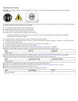
• You must follow the recommended procedures for handling electrostatic discharge (ESD)-sensitive devices.
• No tools are required to complete this task. Do not remove or loosen any screws during this procedure.
• Every drive slot of an operational control enclosure must contain either a drive or a blank filler, and must not
be left empty for more than 10 minutes during servicing.
• IBM FlashCore Modules are not interchangeable with the flash modules that are used in IBM FlashSystem
900 storage enclosures.
Procedure
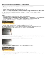
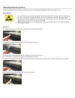
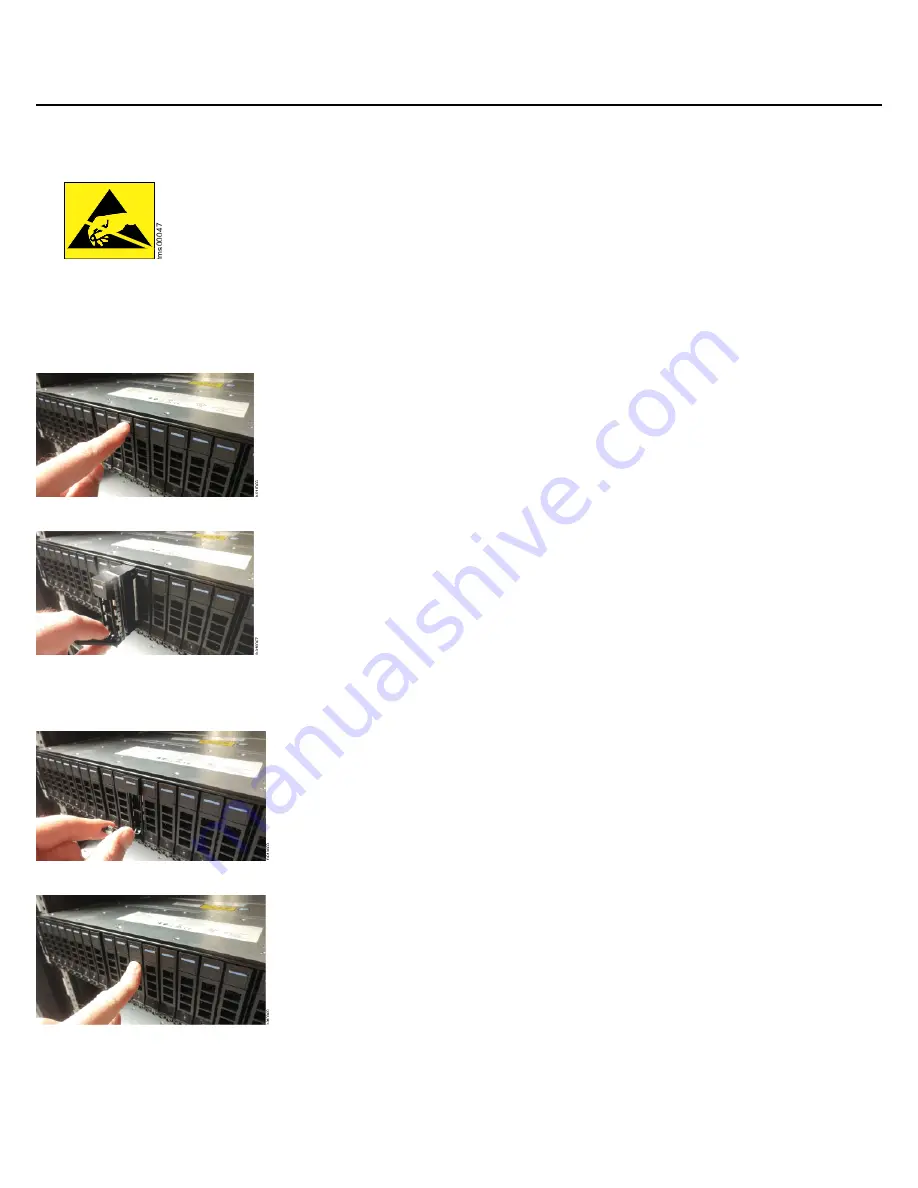
1.
To remove the drive, press the blue touchpoint to unlock the latching handle.
2.
Lower the handle and slide the drive out of the enclosure as shown.
3.
To replace the drive, ensure that the LED indicators are at the top of the drive.
4.
Press the blue touchpoint to unlock the latching handle on the drive.
5.
Slide the drive into the node canister. Press on the drive label near the bottom of the drive to ensure that the drive is fully inserted.
6.
Close the handle on the drive until the latch clicks into place.


