Populate disk slots 96–105 at any time during the sequence, as they are cooled separately within the
enclosure.
Enclosure chassis
The Model 106 chassis consists of a sheet metal enclosure with integrated PCBs and a module runner
system. The enclosure is comprised of a drive channel and a controller channel, and features removable
top cover lids. Enclosure top and rear panels provide access to plug-in modules known as customer-
replaceable units (CRUs). Each enclosure is comprised of sheet steel that is bonded together using rivets,
welding, and other forced contact methods. The metal surfaces are free from non-conductive coatings
and paint.
• The chassis has a 1.2m rack mounting that enables it to be installed onto standard 1.2m racks, and
uses four EIA units of rack space (7") for a Model 106 enclosure. Optional lift handles on the chassis
side walls facilitate hoisting and installation. See also Figure 24 on page 31.
• The Cable Management Arm routes cables from the controller channel and external connections–and
secures them for in-rack servicing of the installed enclosure. The rails slide outward from the installed
position.
• An internal high-speed harness ensures routing of cables controlled to specification; protects the
interfaces between cables and connectors; and provides a connector system designed for positive
(latched) mating.
• The drive channel bus-bar distributes power from power midplane to 24HDD baseplanes.
• Four 24 HDD baseplane PCBs support 96 disk drive connections in the drive channel.
• 10 HDD baseplane PCB supports 10 disk drive connections in the controller channel.
• The enclosure top panel provides access to 106 low profile (1" high) 3.5" LFF or 2.5" SFF (with adapter)
disks, held vertically. Each drive slot holds a plug-in drive carrier module. The top panel also provides
access to the HS expander and controller fan CRUs.
Note: Top panel enclosure lids A and B slide out, and can be temporarily removed for a servicing event.
• Eight removable HS expanders connect to 24 HDD baseplanes via expander link cards, providing high
availability.
• Within the controller channel compartment, channel fans provide additional cooling for IOMs/EBOD
expander modules.
• Within the rear panel, the chassis assembly can hold a maximum of two PSUs, four system fans, two
CFF-compliant IOMs/EBOD expander modules, and the flattened cable coils held by the bracket
assembly on the CMA shelf (atop system fan sheet metal).
Important: If the Model 106 enclosure is configured with a single expansion module, it must be installed
in IOM slot No.0 (as shown in Figure 11 on page 13). An IOM blank must be installed in the adjacent slot
(No.1). This configuration is required to ensure sufficient air flow through the enclosure during operation.
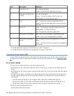
Overview of front panel LEDs
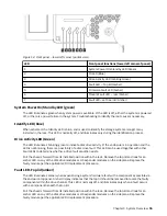
The enclosure front panel displays several LEDs. The front panel displays the functions shown in the
illustration below and listed in the table.
14 IBM ESS expansion: Hardware Installation and Maintenance Guide - Model 106
Содержание 106
Страница 1: ...IBM ESS expansion Version 5 3 5 Hardware Installation and Maintenance Guide Model 106 IBM SC27921101...
Страница 6: ...Russia Electromagnetic Interference Class A Statement 100 Homologation statement 100 vi...
Страница 12: ...xii...
Страница 18: ...xviii IBM ESS expansion Hardware Installation and Maintenance Guide Model 106...
Страница 20: ...2 IBM ESS expansion Hardware Installation and Maintenance Guide Model 106...
Страница 44: ...26 IBM ESS expansion Hardware Installation and Maintenance Guide Model 106...
Страница 53: ...Figure 28 CMA attachment aligned with outer slide Figure 29 Panhead screws Chapter 4 Installation 35...
Страница 84: ...66 IBM ESS expansion Hardware Installation and Maintenance Guide Model 106...
Страница 100: ...82 IBM ESS expansion Hardware Installation and Maintenance Guide Model 106...
Страница 108: ...90 IBM ESS expansion Hardware Installation and Maintenance Guide Model 106...
Страница 119: ......
Страница 120: ...IBM SC27921101...


