Enclosure core product
The design concept is based on an enclosure subsystem together with a set of plug-in modules. A typical
enclosure system—as supplied—includes the following:
• An enclosure chassis equipped with several PCBs, including a midplane, sideplane, and baseplane
PCBs, and a cluster of integral enclosure status LED indicators located at the lower left area of the
enclosure front panel, near the left ear.
• Two 2000W, 200–240V AC power supply unit modules.
• Fan control (system): four system fan modules for enclosure cooling.
• Two interface slots, each of which holds an IOM/EBOD expander module configured with dual CAT5e/6
Ethernet ports (only for diagnostics and service, not available to end user), four ports with four mini-SAS
HD (SFF-8644) connectors, and a serial port.
• Fan control (controller): two controller channel fan modules for IOM/EBOD expander module cooling.
• Up to 106 LFF or SFF disk drive modules with tool-less wrap-around carrier.
• One removable HS expander per row.
• A rail kit for rack mounting.
• A Cable Management Arm (CMA) for managing cables, and enabling in-rack servicing of the enclosure.
Note: About enclosure modules
• The disk modules are not installed when the enclosure ships. Do not insert disks into the enclosure until
after it has been secured in the rack. See also “Populating disk drive slots” on page 13.
• The module quantities quoted above are the maximum that a Model 106 enclosure can support. The
following figures show component locations relative to the enclosure front, rear, and top panels.
• Unless otherwise noted within a passage pertaining to a particular FRU or CRU, the replacement
procedure should be completed within 3 minutes of the removal of a defective module.
• Before rack-mounting enclosures, see CAUTION and WARNING.
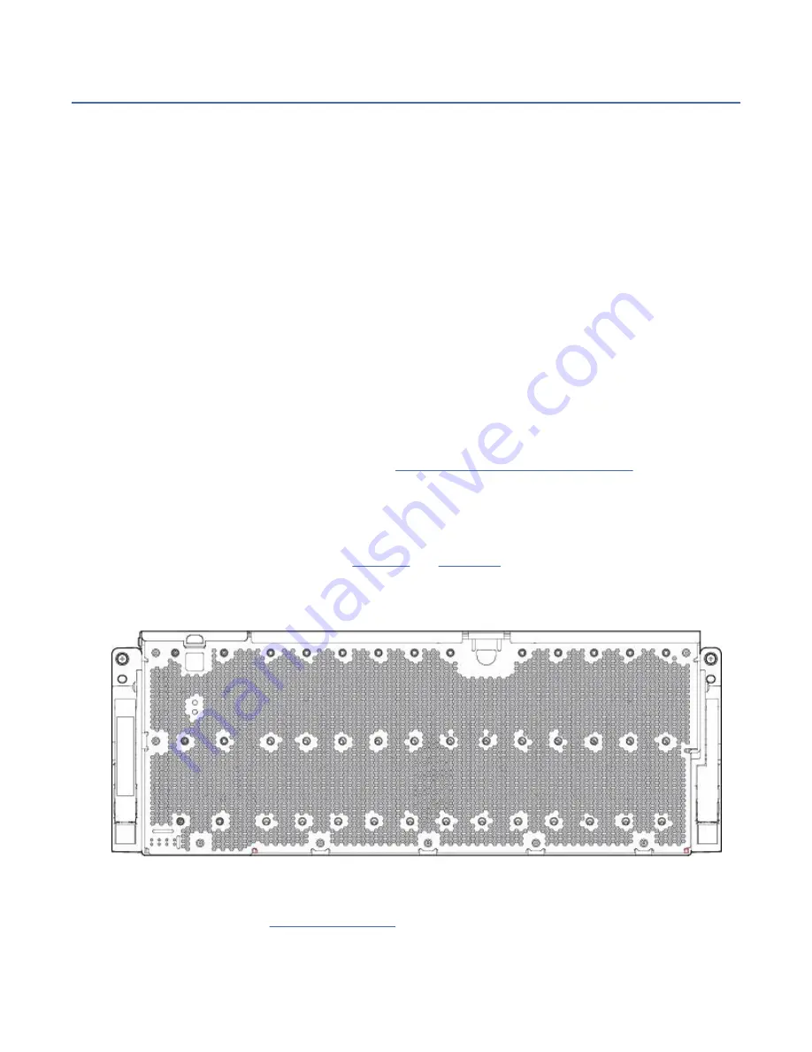
Enclosure front panel
This enclosure front panel view intentionally omits the lift handles that attach to the enclosure sides.
Figure 3. Model 106 enclosure system – front panel components
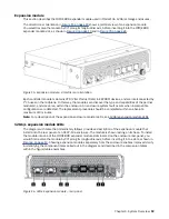
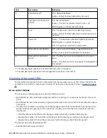
The enclosure front panel provides access to the seven (7) main enclosure system LEDs, located in the
right enclosure pull handles used to slide the enclosure forward for in-rack servicing tasks.
Chapter 3. System Overview 9
Содержание 106
Страница 1: ...IBM ESS expansion Version 5 3 5 Hardware Installation and Maintenance Guide Model 106 IBM SC27921101...
Страница 6: ...Russia Electromagnetic Interference Class A Statement 100 Homologation statement 100 vi...
Страница 12: ...xii...
Страница 18: ...xviii IBM ESS expansion Hardware Installation and Maintenance Guide Model 106...
Страница 20: ...2 IBM ESS expansion Hardware Installation and Maintenance Guide Model 106...
Страница 44: ...26 IBM ESS expansion Hardware Installation and Maintenance Guide Model 106...
Страница 53: ...Figure 28 CMA attachment aligned with outer slide Figure 29 Panhead screws Chapter 4 Installation 35...
Страница 84: ...66 IBM ESS expansion Hardware Installation and Maintenance Guide Model 106...
Страница 100: ...82 IBM ESS expansion Hardware Installation and Maintenance Guide Model 106...
Страница 108: ...90 IBM ESS expansion Hardware Installation and Maintenance Guide Model 106...
Страница 119: ......
Страница 120: ...IBM SC27921101...


