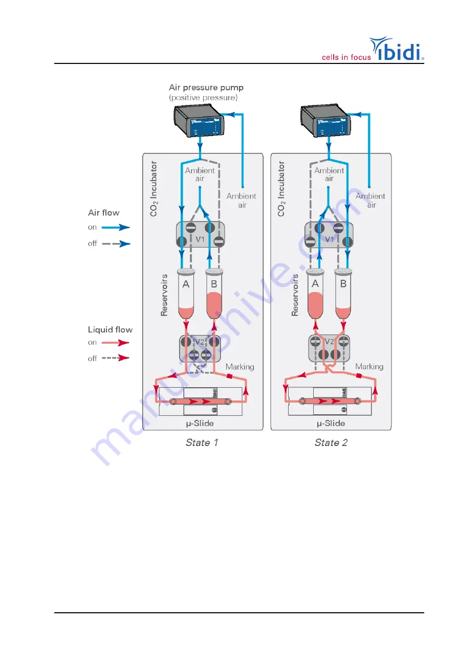
ibidi Pump System
Figure 48: Working principle of the valves creating a unidirectional flow, using
positive
pressure.
Example with positive pressure
In State 1, the valve (V1) is set such that the pressurized air is
applied to reservoir (A), while the outlet of reservoir (B) is opened to the atmosphere. This creates a
flow from reservoir (A) to reservoir (B). Valve (V2) squeezes the two tubing sections in the front slots,
forcing the liquid to flow through the lower loop of the Perfusion Set. The channel is perfused from
left to right.
In State 2 valve (V1) is set such that the pressurized air is applied to reservoir (B) while the outlet
of reservoir (A) is opened to the atmosphere. The apparent flow direction is inverted to a flow from
reservoir (B) to reservoir (A). Valve (V2) also changes state, and now pinches the two tubing sections
in the rear slots, again forcing the liquid to flow through the lower loop. The crossed geometry of the
Perfusion Set again directs the liquid to the channels left inlet, resulting in a perfusion from left to
right.
Instruction Manual
61
Version 2.6 (May 12, 2022)


