9
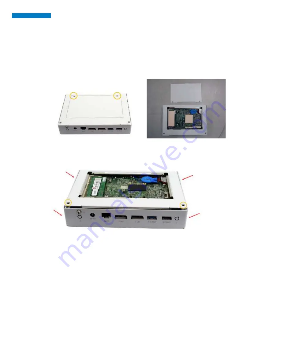
1.5.2 Installing the Optional Wireless Module
1. Remove the two screws on the back cover that are used to secure the cover to the
chassis. Once all the screws are removed, from the side, dismount the cover forward
to remove it.
2. Remove the two screws on the base and four screws on the bracket and draw out
the chassis.
Содержание SI - 83
Страница 1: ...SI 83 User Manual Digital Player Revision Release Date V1 0 2014 12 12...
Страница 6: ...x SI 83 User Manual...
Страница 9: ...3 1 2 2 Dimensions...
Страница 10: ...4 SI 83 User Manual 1 2 3 I O View SI 83 front side SI 83 rear side...
Страница 11: ...5 1 3 Exploded View of the SI 83 Assembly...
Страница 22: ...16 SI 83 User Manual IB983 Jumpers and Connectors...
Страница 23: ...17 Board Dimensions...
Страница 26: ...20 SI 83 User Manual J18 Setting Function Pin 1 2 Short Closed Normal Pin 2 3 Short Closed Clear CMOS...
Страница 28: ...22 SI 83 User Manual CN5 CN8 USB2 0 Connector CN6 CN7 USB3 0 Connector CN9 Gigabit LAN RTL8111G RJ45 Connector...
Страница 30: ...24 SI 83 User Manual J1 J9 DDR3 SO DIMM Socket J4 Mini PCIE Connector J5 mSATA Connector...


