ibaBM-DPM-S-64
Manual
Issue 2.5
21
ibaBM-DPM-S-64 can be inserted anywhere into an existing Profibus DP network. Var-
ious cases are conceivable:
The Profibus cable has two cable ends with end plugs at the point where the device
is to be installed. One end is connected to the Bus0 connection, and the other end
to the Bus1 connection. The switch S6 must then be closed (ON); the terminating
resistors (S4, S5) must be switched off (OFF).
The Profibus cable has a plug and incoming and outgoing wires at the point where
the device is to be installed. The plug can then be plugged onto one of the connec-
tions Bus0 or Bus1. The switch S6 must be opened (OFF).
The Profibus cable has two neighboring plugs with incoming and outgoing wires at
the point where the device is to be installed. Both plugs can be plugged onto the
connectors Bus0 and Bus1. S4, S5, and S6 must be open (OFF).
8.2
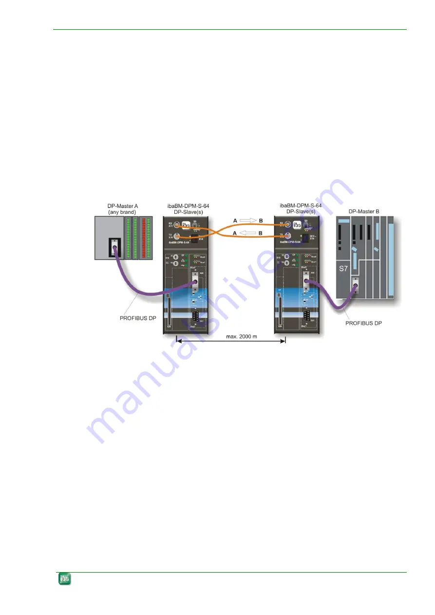
ibaBM-DPM-S-64 for coupling of two DP networks
Figure 5:
ibaBM-DPM-64 connected to DP master, other DP slaves and stationary PC
In case those 2 Profibus DP networks should be linked, maybe over long distances,
two ibaBM-DPM-S-64 provide a solution for up to 64 analog and 64 digital signals in
each direction.
If, moreover, these signals should be measured by an ibaPDA-system, it's easy to in-
stall an ibaBM-FOX-i-3o device in each ibaNet fiber optic line in order to duplicate the
signals for the ibaPDA.


