


UHF1(400-470MHz)
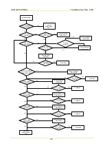
Troubleshooting Flow Chart
27
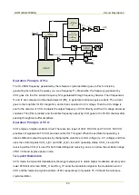
[2] Output voltage by U302 PIN5 or input voltage by Q6004 PIN4 is about 3.3 V.
[3] Vgs: about 0.1 V; Vsd: about 3.3 V (in the case of no signal reception).
[4] For Q6006, Vbe: about 0.76 V; Vce: about 0.95 V; for Q6007, Vbe: about 0.7 V; Vce: 0.85 V (in the
case of no signal reception).
[5] Cut off the front-end circuit, and input a 58.05 MHz IF signal at C6009 to test IF sensitivity. Normally,
the IF sensitivity is -109 dBm.
[6] Frequency of Q6003: 55.8 MHz.
[7] Frequency of L6013: 18 MHz.
[8] Input a -30 dBm RF signal in the antenna port and test at RP1. Normally, gain>10 dB, output
signal>-20 dBm.
[9] Input a -30 dBm RF signal in the antenna port and test at C6092 (do not cut off the back-end circuit).
Normally, gain>1 dB, output signal>-29 dBm.
[10] C6093 output signal frequency: RF-IF, signal amplitude>2 dBm.
[11] For input of a -80 dBm signal from L6028, gain>25 dB, output signal>-55 dBm; for input of a -30
dBm signal, output signal>-20 dBm.
[12] The input signal in the antenna port, with standard tuning information (AF=1 KHz
,
FM=3 KHz), is -47
dBm.
6.3
Transmitter Circuit
Caution
The following checks must be operated with a power supply of 7.4 V.
Содержание PD502
Страница 1: ...PORTABLE...
Страница 5: ...VHF 136 174 MHz...
Страница 13: ...VHF 136 174 MHz Exploded View and Packaging Guide 7 3 2 Packaging Guide...
Страница 18: ...VHF 136 174 MHz Circuit Description 12...
Страница 43: ...PCB 3 9 PCB VHF 136 174 MHz...
Страница 44: ...PCB 3 VHF 136 174 MHz...
Страница 71: ...UHF1 400 470 MHz...
Страница 79: ...UHF1 400 470MHz Exploded View and Packaging Guide 7 3 2 Packaging Guide...
Страница 84: ...UHF1 400 470MHz Circuit Description 12...
Страница 108: ...UHF1 400 470MHz PCB 36 9 PCB...
Страница 109: ...UHF1 400 470MHz PCB 37...
Страница 136: ...1616300000260 2014 03 17 L07157 4...