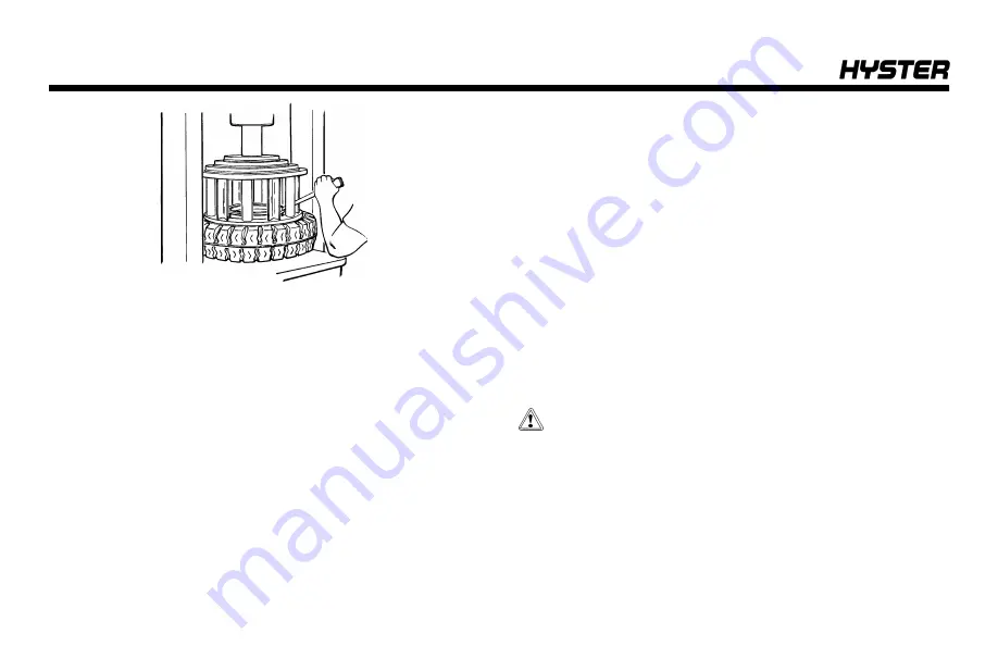
4.
While the cage is holding the tire on the wheel rim, install
the lock ring. Use a tire tool to make sure the lock ring is in
the correct position.
Operating Procedures for a New or Rebuilt
Engine
A new or rebuilt engine must be operated under special
conditions during the first 50 hours. These special condi-
tions prevent damage to the engine until the new parts can
wear and adjust to fit each other.
1.
Make sure the fluid levels of oil and coolant are correct.
2.
Start and run the engine at approximately one-half throt-
tle for 30 minutes for the first operation. Check the gauges
and indicators for the correct operation during this first
operating period. Check for leaks.
3.
If the work conditions are slow and the loads are less
than 50% of the truck capacity, a simulated work condition
must be used during the first four hours of operation. Oper-
ate the lift truck with a minimum load of 75% capacity.
Operate the engine through cycles from idle to full throttle
and back to idle. Avoid long periods of high engine speeds
with a light load during the first 50 hours of operation. High
engine speeds with a light load can cause damage to the
cylinders in the engine.
Jump-Starting the Lift Truck
Jump-Starting Using a Battery Charger
CAUTION
DO NOT try to start the engine by pushing or towing
the lift truck. Damage to the transmission can occur if
engine is started by pushing or towing lift truck.
If the battery becomes discharged and requires a booster
battery to start the engine, follow these procedures care-
fully when connecting the jumper cables:
Maintenance
168
Содержание H40-60XT
Страница 1: ...OPERATING MANUAL H40 60XT A380 DO NOT REMOVE THIS MANUAL FROM THIS UNIT PART NO 4150900 3 19...
Страница 11: ...Model Description Figure 1 Model View Showing Major Components of H40 60XT Model Description 9...
Страница 16: ...Figure 3 Warning and Safety Labels Sheet 1 of 3 Model Description 14...
Страница 17: ...Figure 3 Warning and Safety Labels Sheet 2 of 3 Model Description 15...
Страница 18: ...Figure 3 Warning and Safety Labels Sheet 3 of 3 Model Description 16...
Страница 20: ...Figure 4 Controls Model Description 18...
Страница 42: ...Figure 5 Dash Display Warning and Indicator Lights Model Description 40...
Страница 62: ...Figure 6 Seat Adjustment Operating Procedures 60...
Страница 90: ...1 DRIVE TIRES 2 STEERING TIRES Figure 10 Put a Lift Truck on Blocks Maintenance 88...
Страница 92: ...Figure 11 Maintenance and Lubrication Points PSI 2 4L LPG Trucks Maintenance Schedule 90...
Страница 93: ...Figure 12 Maintenance and Lubrication Points Yanmar 2 6L and 3 3L Diesel Trucks Maintenance Schedule 91...
Страница 94: ...Figure 13 Maintenance and Lubrication Points PSI 2 4L Bi Fuel Trucks Maintenance Schedule 92...
Страница 115: ...Figure 16 Seat Check Maintenance 113...
Страница 120: ...1 FRAME 2 PDM 3 GROUND STATIC STRAP 4 BATTERY Figure 18 Ground Static Strap Maintenance 118...
Страница 137: ...Figure 30 Brake Fluid Reservoir Cover Maintenance 135...
Страница 139: ...Figure 31 PDM Showing Fuses and Relays Maintenance 137...
Страница 178: ...NOTES 176...
Страница 179: ...Spacer 3 19 12 18 7 18 12 17 10 17 5 17 3 17 1 17 11 16 10 16 7 16 5 16 4 16 3 16...
Страница 180: ...OPERATING MANUAL H40 60XT A380 DO NOT REMOVE THIS MANUAL FROM THIS UNIT PART NO 4150900 3 19...


