28
© 2012 Installation and Reference Manual D0125 Rev. H
Section 3
—Installer Menu Functions – continued
Installer 17
[
]
PEO (photo eye open) reverse to close:
The default setting is non-reversal if the open photo eye
is triggered. The optional setting of [
] will cause the gate to reverse to close for two seconds if triggered while opening.
Installer 18
[gr 0]
Edge reverse to open:
The default setting is to reopen fully. The optional setting of [
] sets the
gate at a 2-second reversal if triggered while closing.
Installer 19
[
]
IES (inherent sensor) reverse to open:
The default setting is a 2-second duration reversal if the
inherent sensor is triggered. The optional setting of [
] will cause the gate to reopen fully if triggered while closing.
Installer 20
[
]
Set PEO/ PEC
– NO/NC:
The default setting is photo eyes with Normally Open outputs. The
optional setting [
] will require a Normally Closed (NC) output. If set for NC, the connection is also supervised and any
open or short circuit fault will generate a FAL2 alert, which requires a Stop button reset to re-enable any function if
triggered.
Installer 21
[
]
Set Edge input
– NO/NC:
The default setting is edge sensor with Normally Open (NO) outputs. The
optional setting [
] will require a NC output..
Installer 22
[
]
Time clock / Interlock input:
This menu item configures the input at terminal #7 to be either for the
gate interlock function, as described on page 29, or for an external time clock to open input, as described on page
Error!
Bookmark not defined.
. The default setting is [
for the interlock function.
Installer 23
[
]
Disable Free Exit / Close timer:
Configures the input at Terminal No. 9 on the controller circuit board
to disable either the Free Exit Detector on terminal #8, or the Timer To Close function. Default setting is [
] allowing
disabling of the free exit detector.
NOTE
: The free exit is disabled when the gate is at its closed limit. If the closed limit is not tripped, the free exit continues
to work.
Installer 24
[
]
OOLD (Outside Obstruction Loop Detector) function:
The default is for full reversal when the
OOLD is triggered. The optional setting [
] causes the gate to only pause when triggered. Gate closure begins as
soon as the loop is clear again.
Installer 25
[
]
IOLD (Inside Obstruction Loop Detector) function:
The default is for full reversal when the IOLD
is triggered. The optional setting [
] causes the gate to only pause when triggered. Closure begins as soon as the
loop is clear again.
Installer 26
[
]
Vehicle detector logic:
Configures quick close and anti-tailgate logic. There are four modes. See the
full description on page 45.
Installer 27, 28, 29
[
], [
], [
]
User output relay 1 - 3 options:
Configures the function of the three user
output relays. There are 21 optional choices, which are described in detail on page 30.
Installer 30
[
]
Gate Open alert:
Adjusts the time delay before activating the user relay function #8, described on
page 30. Time settings up to 135 seconds.
Installer 31
[
]
Loitering alert:
This menu item is to adjust the time delay before activating the user relay function
#13, described on page 30. Time settings up to 135 seconds.
Installer 32
[
]
System Address:
Sets the system address for network communication; 0 = no network
communication, 1-99 sets individual poling addresses. Requires v4.24 software or higher.
Installer 33
[
]
Factory ELD:
Controls the HY-5A Free Exit detector, see page 44.
Installer 34
[
]
Factory IOLD:
Controls the HY-5A IOLD detector, see page 44.
Installer 35
[
]
Factory OOLD:
Controls the HY-5A OOLD detector, see page 44.
Installer 36
[SLd].
Factory SLD:
Controls the HY-5A Shadow detector, see page 44.
Содержание SlideDriver 50VF2
Страница 2: ......
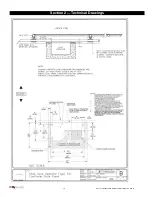
Страница 28: ...14 2012 Installation and Reference Manual D0125 Rev H Section 2 Technical Drawings...
Страница 29: ...15 2012 Installation and Reference Manual D0125 Rev H Section 2 Technical Drawings...
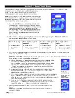
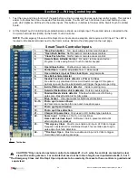
Страница 36: ...22 2012 Installation and Reference Manual D0125 Rev H Section 3 Wiring Control Inputs...
Страница 54: ...40 2012 Installation and Reference Manual D0125 Rev H Section 5 Detector Loop Installation continued...
Страница 63: ...49 2012 Installation and Reference Manual D0125 Rev H Section 6 Internal Solenoid Lock Drawing...
Страница 64: ...50 2012 Installation and Reference Manual D0125 Rev H Section 6 Internal Solenoid Lock Drawing...
Страница 80: ...67 2012 Installation and Reference Manual D0125 Rev H Appendix 50VF2 3 Control Box STC and Component Wiring...
Страница 81: ...68 2012 Installation and Reference Manual D0125 Rev H...


