background image

HyPrecision15/30/50

 Operator 

Manual 808240

71

5 –  Preventive maintenance

Preventive maintenance

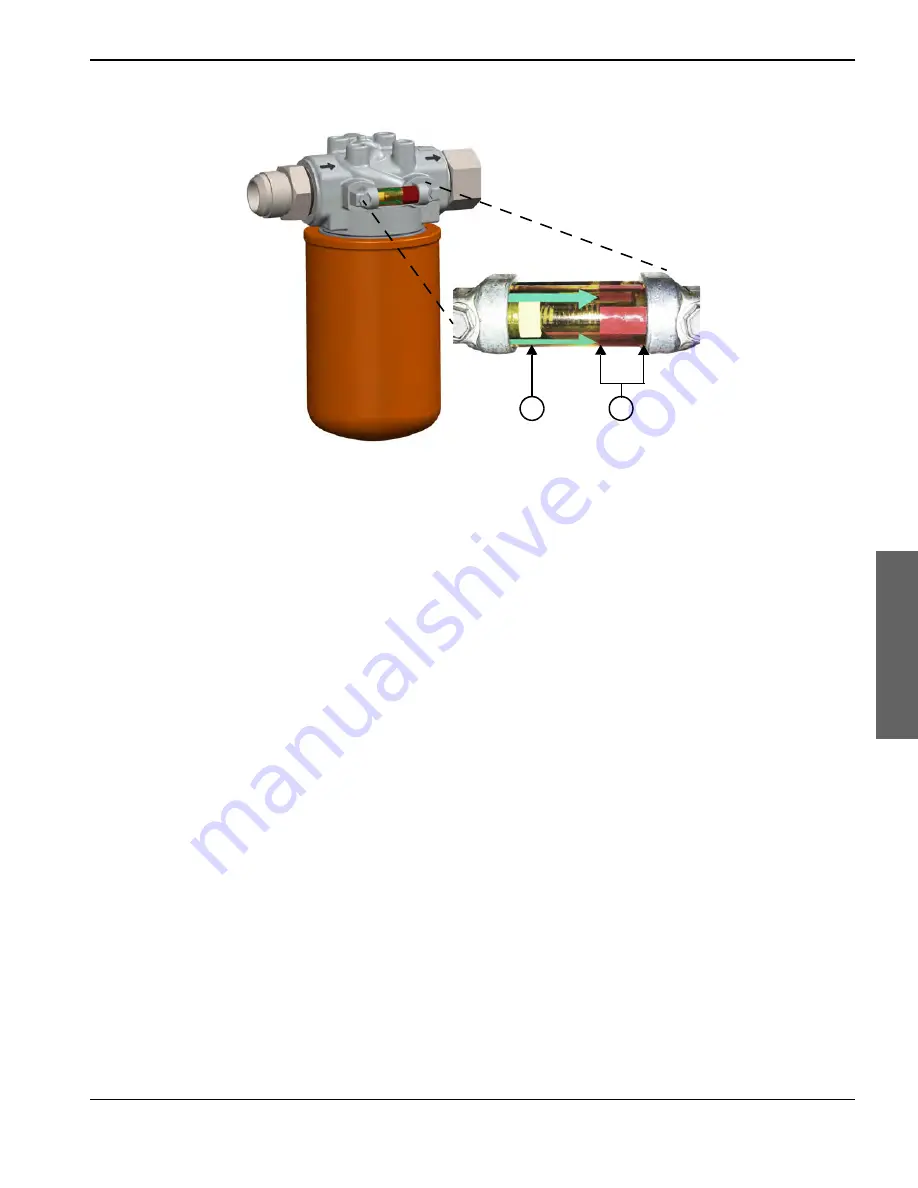
Check the hydraulic fluid indicator

Replace the filter after every 1,500 hours of operation.

Replace the filter when the white indicator stays in the red zone while the pump is running at operating temperature. 
Refer to page 92 for instructions.

1

2

1

White indicator

2

Red zone

Содержание HyPrecision 15

Страница 1: ...HyPrecision15 30 50 Waterjet Pump Operator Manual 808240 Revision 1 English ...

Страница 2: ...recision and Hypertherm are trademarks of Hypertherm Inc and may be registered in the United States and other countries All other trademarks are the property of their respective holders 2015 Hypertherm Inc ...

Страница 3: ...HyPrecision15 30 50 Operator Manual 808240 Revision 1 English Original Instructions July 2015 Hypertherm Inc Hanover NH 03755 USA www hypertherm com ...

Страница 4: ...58 Fax Australia and New Zealand 61 0 7 3103 1695 61 0 4 3760 6995 Mobile 61 0 7 3219 9012 Fax Europe Middle East and Africa Technical service 00 800 4973 7843 Toll free 31 0 165 596900 31 0 165 596906 Fax TechnicalService HyperthermEurope Hypertherm com Customer service 00 800 3324 9737 Toll free 31 0 165 526156 00 800 4973 7329 Toll free fax 31 0 165 596948 Fax Return materials 31 0 165 596936 3...

Страница 5: ...ypertherm products SC 17 Proper handling and safe use of chemicals SC 17 Particle emission and wastewater quality SC 17 Safety SC 19 User qualification and training SC 19 Emergency medical information and treatment SC 20 Symbols and marks SC 21 Information and hazard symbols SC 21 Symbols and marks found on the data plate and the pump SC 22 1 Terminology 25 2 Product description 29 Pump exterior 3...

Страница 6: ...e end of the day 59 5 Preventive maintenance 61 Benefits of preventive maintenance 61 Safety 62 Tips 63 Preventive maintenance schedule 64 Tools 66 Complete list of preventive maintenance kits parts tools and materials 67 Every shift 68 Every 40 hours 76 Every 500 hours 78 Every 1 000 hours 85 Every 1 500 hours 92 Every 2 000 hours 93 Every 3 000 hours 94 Every 6 000 hours 100 Every 12 000 hours 1...

Страница 7: ... problems 155 Leaks 159 Short seal life 160 Hydraulic fluid 161 Low pressure 161 High temperature 161 Low water pressure 163 From the intensifier 163 To the intensifier 163 Motor fault 164 8 Pump specifications 165 HyPrecision 15 166 HyPrecision 30 167 HyPrecision 50 168 All models 169 Hydraulic fluid 169 Operating conditions 169 Cooling requirements 169 Utility fittings 170 Torque values 171 Fast...

Страница 8: ...0 Air 180 Water 181 Receive and unpack the pump 183 Install the external heat exchanger 184 Make the connections for remote operation 184 Make the connections to the utility panel 186 Add hydraulic fluid 187 Connect the electrical power 188 Do the first startup 189 Recycling and end of product life 193 ...

Страница 9: ... number is on the data plate which is found above the connection panel on the back of the pump System schematic drawing number The system schematic drawing number is found on the data plate and inside the electrical enclosure door on a green label Purchase date Distributor Installation date Installed by Notes ...

Страница 10: ...10 HyPrecision15 30 50 Operator Manual 808240 Pump information Pump information ...

Страница 11: ...ths from the date of proven installation or 4 000 hours whichever occurs first Bulk abrasive hoppers 15 months from the ship date or 12 months from the date of proven installation whichever occurs first Abrasive regulators abrasive metering devices 15 months from the ship date or 12 months from the date of proven installation whichever occurs first On off valve air actuators 15 months from the shi...

Страница 12: ...SC 12 Safety and compliance Warranty Warranty ...

Страница 13: ...laboratory Once the product has left the Hypertherm factory the certification test marks are invalidated if any of these events occur The product is modified in a manner that creates a hazard or nonconformance with the applicable standards Safety critical parts are replaced with unauthorized spare parts Assembly is unauthorized An accessory that uses or generates a hazardous voltage is added There...

Страница 14: ...6 95 EC European Low Voltage Directive 2004 108 EC European Electromagnetic Compatibility EMC Directive This declaration is not valid on units without a CE mark on the data plate For European customer inquiries contact European Customer Service Hypertherm Europe B V Vaartveld 9 4704 SE Roosendaal the Netherlands 31 0 165 596907 To see the signed Declaration of Conformity in English go to the Hyper...

Страница 15: ...rjet cutting system the combined system can be considered a higher level system A higher level system with hazardous moving parts can constitute industrial machinery or robotic equipment in which case the system integrator or end use customer could be subject to more regulations and standards than those relevant to the waterjet cutting system as manufactured by Hypertherm It is the responsibility ...

Страница 16: ...SC 16 Safety and compliance Product stewardship Product stewardship ...

Страница 17: ...zard Communication Standard 29 CFR 1910 1200 to align with the United Nations Globally Harmonized System of Classification and Labelling of Chemicals GHS The GHS is an international system for standardizing chemical classification and labeling Chemical regulations in the USA Europe and other locations require that Material Safety Data Sheets MSDS and Safety Data Sheets SDS be made available for ch...

Страница 18: ...SC 18 Safety and compliance Environmental stewardship Environmental stewardship ...

Страница 19: ...afety standards The use limitations and care of personal protective equipment The location of the written hazard communication program and safety data sheets How to recognize hazardous energy sources The correct methods for isolating and controlling energy including lock out tag out procedures User qualification and training All users must read and understand these instructions before installing o...

Страница 20: ...A high pressure injection injury is a surgical emergency Seek immediate medical treatment for all high pressure waterjet injuries Delayed treatment can lead to serious injuries or death The person carrying this card has been exposed to a waterjet of up to 4 137 bar 60 000 psi and a velocity of 609 m s 2 000 feet second The waterjet can contain abrasive materials Skin can appear intact or show a mi...

Страница 21: ...death High pressure water can cause eye injuries Wear approved eye protection when operating or working near this equipment Prolonged exposure to noise can cause permanent hearing loss Wear approved ear protection and control exposure time when operating or working near this equipment High pressure water can cause severe cuts or lacerations abrasions and punctures Wear approved hand protection whe...

Страница 22: ...stem Hz Frequency hertz FLA Full load current amperage SCCR Short circuit current rating IP Ingress protection rating Imax Primary motor maximum current draw amperes kW Primary motor power output kilowatts l min Maximum outlet flow rate liters minute MPa Maximum outlet water pressure megapascals DWG System schematic drawing number The Conformité Européene CE mark shows that a product complies with...

Страница 23: ...fluid that is sent to an external air cooler CUTTING WATER IN Low pressure water from a softener or reverse osmosis system that goes to the intensifier also called inlet cutting water CUTTING WATER OUT High pressure water from the intensifier that is used for cutting or piercing WASTEWATER OUT Water from the bleed down valve or the low pressure system that goes to a drain Prefilter water pressure ...

Страница 24: ...SC 24 Safety and compliance Symbols and marks Symbols and marks ...

Страница 25: ...on of a machine tool cooling water Low pressure water that circulates through the heat exchanger to cool the hydraulic fluid cSt A centistoke is a measurement of kinematic viscosity water has a viscosity of 1 centistoke or 1 mm2 second cut pressure mode high pressure mode Water that is at cutting pressure cutting water cutting water out High pressure water from the intensifier that is used for cut...

Страница 26: ...d are composed of a fitting a flare nut and a sleeve kPa A kilopascal is a unit of pressure 1 kPa equals 0 01 bar or 0 15 psi or 1 000 N m2 lap To rub a stainless steel surface against lapping paper to make the surface very smooth and flat lockout tagout Lockout tagout procedures protect workers from the unexpected starting of machinery and equipment and the release of hazardous energy during main...

Страница 27: ...de Hypertherm products that are sold directly to end users reverse osmosis A method for treating water by forcing it through a semipermeable membrane to remove impurities that can damage high pressure parts SAE SAE International is a professional association of engineers and technical experts that coordinates the development of technical standards based on best practices in the aerospace commercia...

Страница 28: ...28 HyPrecision15 30 50 Operator Manual 808240 Terminology Terminology ...

Страница 29: ...t cutting Four systems make up the pump hydraulic low pressure water high pressure water and electrical These systems are not independent of each other Color is used throughout the manual to identify the different systems In the Preventive maintenance section which begins on page 61 red is also used to highlight applicable parts 1 2 3 4 1 High pressure water system green 2 Hydraulic system gold 3 ...

Страница 30: ...7 5 bar or 276 kPa to 758 kPa 40 psi to 110 psi Postfilter water pressure gauge The postfilter gauge shows the pressure after the water goes through the filters Normal operating range is 2 8 bar to 7 5 bar or 276 kPa to 758 kPa 40 psi to 10 psi Hydraulic pressure gauge This gauge shows the hydraulic pressure in the pump 1 2 4 5 6 7 8 3 1 Side cover 2 Top deck 3 Electrical enclosure 4 Operator inte...

Страница 31: ...description Product description To determine the approximate cutting water pressure multiply the hydraulic pressure gauge value by 20 Hydraulic pressure Cutting water pressure Example 4 100 bar 20 82 000 bar 41 000 kPa 20 820 000 kPa 3 000 psi 20 60 000 psi ...

Страница 32: ... the intensifier where it is compressed by the piston to make high pressure water for cutting or piercing Hydraulic fluid from the hydraulic center section in the intensifier returns to the hydraulic fluid tank through the primary hydraulic manifold The heat exchanger keeps the hydraulic fluid at its optimal temperature A gear pump moves hydraulic fluid from the hydraulic fluid tank and sends it t...

Страница 33: ...ess to the tank for adding hydraulic fluid A sight gauge permits observation of the hydraulic fluid level and quality A temperature and level sensor monitors the hydraulic fluid Suction strainers prevent contaminants from entering the primary pump and the gear pump Open the ball valve to drain the tank 1 2 3 4 5 1 Sight gauge 2 Temperature and level sensor 3 Filler breather cap 4 Drain 5 Suction s...

Страница 34: ...gnals a shift valve to direct the flow of pressurized hydraulic fluid to alternating sides of the piston in the intensifier Ceramic plungers connected to each side of the piston extend into the left and right high pressure ends Hydraulic fluid pushes the piston to 1 side while low pressure water fills the empty cylinder The plunger on the opposite side of the cylinder compresses high pressure wate...

Страница 35: ... pressure on and off A hydraulic pressure gauge shows the pressure in the manifold Pressure compensator The pressure compensator controls cutting water pressure by limiting the minimum and maximum hydraulic fluid pressure to the intensifier The compensating valve limits the maximum pump pressure The differential pressure valve limits the minimum hydraulic pressure 1 2 3 1 Hydraulic control manifol...

Страница 36: ...y motor is running cooling water circulates through the heat exchanger transferring heat away from the hydraulic fluid to the cooling water Air cooled external heat exchanger optional The gear pump directs hydraulic fluid to an external radiator When the temperature of the hydraulic fluid in the hydraulic fluid tank is higher than 54 4 C 130 F a fan forces ambient air over cooling fins to cool the...

Страница 37: ...to remove contaminants Water pressure gauges show the water pressure before and after water goes through the filters A low pressure water switch after the filters tells the programmable controller if the water pressure is higher than the minimum required Filtered water collects in the accumulator which equalizes the water pressure The water enters the high pressure ends in the intensifier where it...

Страница 38: ...al utility or a chiller COOLING IN circulates through the heat exchanger drawing heat away from the hydraulic fluid Water from the heat exchanger exits the cooling system to a drain or is recycled to a chiller COOLING OUT Hydraulic temperature is controlled by adjusting the flow rate of the cooling water with a manual ball valve or an optional water modulating valve 1 2 1 Heat exchanger 2 Ball val...

Страница 39: ...re fluctuations caused by reversal of the intensifier High pressure ends Ceramic plungers connected to each side of the piston extend into the left and right high pressure cylinders Hydraulic fluid pushes the piston to 1 side while inlet cutting water fills the empty cylinder The plunger on the opposite side of the cylinder compresses high pressure water for cutting or piercing Bleed down valve Th...

Страница 40: ...ing When hydraulic fluid forces the piston to the end of the hydraulic center section the piston pushes against a spring loaded indicator pin A signal from the proximity sensor above the indicator pin causes the shift valve in the primary hydraulic manifold to change the direction of the intensifier 1 2 3 4 5 6 7 1 Proximity switches 2 Hydraulic control solenoid 3 Low pressure water switch 4 Shift...

Страница 41: ...ack light illuminates when the system detects a warning or fault condition The operator interface is a programmable controller for the pump and the intensifier A series of screens permits the operator to turn the pump on and off and to change some pump settings The primary screen shows information about warnings and faults The primary breaker disconnect lever disconnects electricity to the pump mo...

Страница 42: ...ted to the bottom of the contactor The HyPrecision 50 model contains a wye delta reduced voltage starter When the primary motor is turned on the primary and wye contactors reduce the initial voltage to the starter The starter runs until the timer expires The timer is set at the factory to 3 seconds The timer relay transfers power to the delta and primary contactors which run at full voltage and to...

Страница 43: ...pped with a water cooled heat exchanger In an air cooled configuration the temperature sensor in the hydraulic fluid tank turns on an external air cooled heat exchanger Water modulating valve Standard pumps are equipped with a ball valve that permits manual adjustment of the cooling water The water modulating valve replaces the ball valve A temperature sensor in the hydraulic fluid tank signals th...

Страница 44: ...44 HyPrecision15 30 50 Operator Manual 808240 3 Options Options ...

Страница 45: ...NING Do not touch a hot surface Fittings can get hot especially when they are not properly tightened CAUTION If a water line fitting or valve might be frozen do not operate the pump Thaw the system until water moves freely through the entire water circuit High pressure water can cause eye injuries Wear approved eye protection when operating or working near this equipment This waterjet system might...

Страница 46: ...r are on the outside of the electrical enclosure Stack light The stack light illuminates when the system detects a warning or fault condition The amber stack light blinks to signal a condition that requires attention The red stack light blinks to show that a fault has occurred Some materials can produce airborne contaminants or suspended particles when cut Wear approved respiratory protection Exam...

Страница 47: ...nside the pump on and off and switches between local and remote pump operation The CONTROLS ON button turns on the controls The controls must be on to operate the pump The EMERGENCY STOP pushbutton turns off the control circuit inside the pump which turns off the pump primary motor and intensifier and opens the bleed down valve to discharge high pressure water from the system When the LOCAL REMOTE...

Страница 48: ...se of a fault correct the fault 2 If the pump turned off because the EMERGENCY STOP pushbutton was pressed reset the pushbutton on the operation panel by turning it in the direction of the arrows clockwise until it pops out 3 Make sure that the water to the pump is turned on Check the water lines for leaks 4 Make sure that the electrical main is turned on 5 Make sure that the primary breaker disco...

Страница 49: ... the REMOTE position the following states are true The remote source such as a computer numerical control CNC operator console controls the pump The REMOTE ACTIVE indicator light is on The CONTROLS ON button is not active Most normal operation from the operator interface is disabled The only option available on the operator interface is the PUMP OFF function 2 If the pump is connected to a remote ...

Страница 50: ...s Hypertherm Inc recommends taking these actions to prevent operator injury and equipment damage Read and understand the instruction manual supplied by the OEM or the system integrator Maintain a restricted access area larger than the maximum movement range of the cutting system s moving parts Where there is a risk of a collision do not permit people or equipment near the cutting system s moving p...

Страница 51: ... Operation Operation Alarm screens When the programmable controller detects a fault condition an alarm screen shows information about the problem and the stack light blinks If this occurs refer to the Troubleshooting section which begins on page 153 ...

Страница 52: ...rn on the pump and the intensifier Press F2 to turn on the pump in cooling mode Press 1 on the numeric keypad to go to the intensifier settings screen Primary screen Pump off Pump running screen Pump on Intensifier on Cooling mode screen Pump on Intensifier off Intensifier settings screen Pump off ...

Страница 53: ... 1 on the numeric keypad to change to pierce pressure or cut pressure mode The screen also shows the intensifier stroke rate Pump running screen Pump on Intensifier on Primary screen Pump off Cooling mode screen Pump on Intensifier off Pump on in pierce pressure mode Intensifier on Pump on in cut pressure mode Intensifier on 1 2 3 1 Pump symbol 2 Pump pressure mode indicator 3 Intensifier stroke r...

Страница 54: ... the pump running in pierce pressure mode Required tools materials and parts 1 2 inch open ended wrench 1 Use an open ended wrench to loosen the jam nut behind the pierce pressure adjustment knob 2 Turn the pierce pressure adjustment knob to the right clockwise to increase the pierce pressure Turn the pierce pressure adjustment knob to the left anticlockwise to decrease the pierce pressure 3 Tight...

Страница 55: ...n ended wrench for a compensator without a cap 3 mm hex wrench Do this with the pump running and the intensifier disabled Refer to page 57 for instructions for disabling and enabling the intensifier 1 If the compensator has a cap remove it The sealing washer under the cap might stick to the cap The compensator will leak if the washer is not in position when the cap is installed 2 Use an open ended...

Страница 56: ...r Press F2 to turn off the pump Press 1 on the numeric keypad to shift the intensifier to the left Press 2 on the numeric keypad to shift the intensifier to the right Cooling mode screen Pump on Intensifier on Pump running screen Pump on Intensifier on Primary screen Pump off Shift the intensifier to the left Shift the intensifier to the right 1 2 1 Cooling symbol 2 Intensifier enabled symbol ...

Страница 57: ...r to adjust the overstroke percentage Adjust the overstroke percentage 1 Press enter The overstroke percentage and the intensifier symbol blink 2 Use the numeric keypad to change the overstroke percentage 3 Press enter to accept the change Intensifier settings screen Pump off Intensifier enabled Intensifier disabled Change the overstroke percentage Primary screen Pump off ...

Страница 58: ...rned on remotely EMERGENCY STOP The EMERGENCY STOP pushbutton is available on the operation panel and at the remote control source If the pump is running this turns off the pump PUMP ON This turns on the primary motor the supply water the cooling fan and the fan starter motor The cooling fan is optional for air cooled pumps The intensifier strokes in pierce pressure mode for a time that is set at ...

Страница 59: ...tensifier to turn off The bleed down valve opens and discharges high pressure water from the system The CONTROLS ON button indicator light turns off Routine stop during operation 1 Turn OFF the cutting head 2 Press F1 on the operator interface to turn off the primary motor The bleed down valve opens and discharges high pressure water from the system Routine stop at the end of the day 1 Turn OFF th...

Страница 60: ...60 HyPrecision15 30 50 Operator Manual 808240 4 Operation Operation ...

Страница 61: ...ve and scheduled maintenance for HyPrecision pumps High quality equipment that is serviced on a schedule lasts longer than equipment that is not regularly maintained This maintenance includes but is not limited to adjustments cleaning lubrication repairs and replacement of parts Benefits of preventive maintenance Improves reliability Finds potential problems before they cause unplanned downtime an...

Страница 62: ... protective equipment are recommended Failure to wear personal protective equipment can result in injuries or death WARNING Use a piece of cardboard or other solid material to find leaks when the pump is operating Do not use hands cloth paper or towels WARNING Do not repair a leak with high pressure water in the system Discharge all high pressure water before working on this equipment WARNING Do n...

Страница 63: ...ing and end of product life on page 193 Follow all safety requirements and applicable safety laws and regulations Coordinate preventive maintenance and repair activities with operations and safety staff Examine and clean the pump regularly Make repairs promptly Use proper tools for maintenance procedures Some tools are designed to make the procedure easier and to prevent damage to the pump People ...

Страница 64: ...al system Make sure that the emergency stop pushbutton works Examine cords and plugs for deterioration or damage Low pressure system Examine the pump for leaks or damage Check the low pressure water pressure gauges Measure the pressure in the water accumulator tank Replace the water filters Test the low pressure water TDS level Hydraulic system Examine the pump for leaks or damage Check the hydrau...

Страница 65: ...lace the hydraulic rod seals Repair the high pressure cylinders Replace the high pressure poppet assemblies Replace the low pressure poppets and poppet springs Replace the check valves Replace the low pressure poppet baskets Replace the high pressure cylinders Replace the plunger bearings Replace the indicator pin springs Replace the output adapters Replace the seal housings Replace the indicator ...

Страница 66: ...ecial tools This page is intended to help a user identify tools that could be unfamiliar or are known by other names Seal housing removal tool included in the HyPrecision standard tool kit Open ended wrench Open ended crowfoot wrench Dental pick Seal installation tools included in the HyPrecision standard tool kit 1 Sleeve 3 Push tool 2 Spacer 4 Locator 1 2 3 4 ...

Страница 67: ...bber mallet Infrared thermometer Air pressure gauge Schrader valve Compressed air source Dental pick recommended 11210 30 30 micron lapping paper 11111 Blue Goop high pressure antiseize lubricant 11448 AccuGoop food grade high pressure antiseize lubricant 11447 High vacuum grease 11136 Silicone based high vacuum grease 13186 White lithium grease antiseize bolt lubricant 13969 Petroleum based O rin...

Страница 68: ...turns off Examine cords and plugs for deterioration or damage Do this task when the pump is not running 1 Examine electrical cords for kinks or damage to the insulation 2 Examine electrical plugs and other electrical connectors for corrosion or damage DANGER People who maintain and repair this equipment can be injured or killed if hazardous energy is not properly controlled Injuries can include bu...

Страница 69: ...aks Water seeping from a weep hole is a sign of a faulty part a loose connection or a damaged connection If a leak is found identify the source and repair the problem Refer to the Troubleshooting section which begins on page 153 If a fitting is not tight high pressure water can cause the fitting to become hot WARNING Use a piece of cardboard or other solid material to find leaks when the pump is o...

Страница 70: ...mal operating range is 3 bar to 8 bar or 276 kPa to 758 kPa 40 psi to 110 psi 1 Look at the gauges 2 Replace the water filters if the postfilter water pressure is lower than 3 bar or 276 kPa 40 psi 3 Subtract the postfilter water pressure from the prefilter water pressure Replace the water filters if the difference between the values on the pre and postfilter water pressure gauges is higher than 1...

Страница 71: ...intenance Check the hydraulic fluid indicator Replace the filter after every 1 500 hours of operation Replace the filter when the white indicator stays in the red zone while the pump is running at operating temperature Refer to page 92 for instructions 1 2 1 White indicator 2 Red zone ...

Страница 72: ...ntenance Preventive maintenance Check the hydraulic fluid level Sight gauge Do this task when the pump is running 1 Make sure that the hydraulic fluid level is at the top mark on the sight gauge 2 Add hydraulic fluid if necessary Refer to page 73 for instructions ...

Страница 73: ... tools materials and parts ISO viscosity grade VG 32 or 46 antiwear mineral or synthetic hydraulic fluid Recommended materials Clean funnel Do this task when the pump is not running 1 Make sure that the drain valve is closed 2 Remove the filler breather cap on top of the tank 3 Fill the tank with hydraulic fluid until the fluid is at the top mark on the sight gauge 4 Install the original filler br...

Страница 74: ...n valve is closed 2 Look through the sight gauge to see the color of the hydraulic fluid Good hydraulic fluid is almost clear 3 Remove the filler breather cap on top of the tank 4 Smell the hydraulic fluid Good hydraulic fluid has almost no odor 5 Replace the hydraulic fluid in these situations If it is dark or milky in color If it has a strong odor After every 3 000 hours of operation Refer to pa...

Страница 75: ...r damage Weep holes Do this task when the pump is running 1 Remove the rear pump panel 2 Examine the bleed down valve for leaks If a leak is found identify the source and repair the problem Refer to the Troubleshooting section which begins on page 153 CAUTION Failure to correct the cause of a leak can result in damage to the fittings ...

Страница 76: ... is too hot can deteriorate and cause the pump to fail Hydraulic fluid that is too cool causes the pump to operate sluggishly Required tools materials and parts Infrared thermometer Do this task when the pump is running Point an infrared thermometer at the middle of the hydraulic fluid tank The optimal operating temperature is 40 6 C 105 F to 46 1 C 115 F If the temperature is outside of this rang...

Страница 77: ...t the hydraulic fluid temperature to stabilize 3 Check the temperature 4 Repeat this procedure until the temperature is in range Water cooled with a water modulating valve 1 Turn the screw on the top of the water modulating valve 1 2 turn to the left anticlockwise to increase the temperature Turn the screw on the top of the valve 1 2 turn to the right clockwise to lower the temperature Adjusting s...

Страница 78: ... Required tools materials and parts Air pressure gauge Schrader valve Compressed air source Do this task when the pump is not running 1 Turn OFF the water to the pump 2 Open the valve to drain the water from the system Make sure that the water pressure gauges show 0 bar or 0 kPa 0 psi Water valve in open position 1 2 1 Accumulator tank 2 Water pressure gauges ...

Страница 79: ...easure the pressure in the water accumulator The optimum air pressure is 2 bar or 207 kPa 30 psi To reduce the pressure press the valve stem to release air from the accumulator Add compressed air to increase the pressure 5 Repeat this procedure until the pressure is 2 bar or 207 kPa 30 psi 6 Install the original valve stem cap 7 Close the water valve Water valve in closed position ...

Страница 80: ...ools materials and parts 12 micron lapping paper included in the HyPrecision standard tool kit 15 micron lapping paper included in the HyPrecision standard tool kit Granite surface plate included in the HyPrecision standard tool kit Clean lint free towel Isopropyl alcohol Masking tape 1 Disassemble the intensifier to access the parts Refer to page 104 for instructions 2 Tape a sheet of lapping pap...

Страница 81: ...the flat face of the part 45 5 Repeat this procedure until the face is smooth and flat and has a nearly mirrored finish 6 Clean each part with a lint free towel and isopropyl alcohol 7 When all maintenance tasks are complete reassemble the parts Refer to page 111 for instructions CAUTION Rocking the part or using too much pressure can damage the part face Do not use soap detergent or solvents 1 2 ...

Страница 82: ...s on page 147 for part numbers and ordering information Required tools materials and parts 15563 HyPrecision premium high pressure seal kit 1 Disassemble the intensifier to access the parts Refer to page 104 for instructions 2 Discard the used parts 3 Install the new parts 4 When all maintenance tasks are complete reassemble the parts Refer to page 111 for instructions Repair or replace parts iden...

Страница 83: ...micron lapping paper Clean lint free towel Nonstick scouring pad Isopropyl alcohol Emery cloth 1 Disassemble the intensifier to access the parts Refer to page 104 for instructions 2 Put the cylinder on a flat surface 3 Examine the end of the cylinder If the area outside of the bore is marked or pitted rub the defects with an emery cloth and then a nonstick scouring pad 4 Examine the edges of the c...

Страница 84: ...t the lapping paper to make 2 pieces each approximately 3 cm 1 1 4 inches wide by 8 cm 3 1 4 inches long 7 Put the lapping paper into the ends of the cylinder with the abrasive side touching the cylinder 8 Repeat the rolling procedure with the lapping paper 9 Clean the inside of the cylinder thoroughly with a lint free towel and isopropyl alcohol 10 When all maintenance tasks are complete reassemb...

Страница 85: ...artridge 0 45 micron 10 inch 11106 Water filter cartridge 1 0 micron 10 inch Water filter wrench included in the HyPrecision standard tool kit Recommended materials Bucket or pail CAUTION Failure to correct the cause of a leak can result in damage to the fittings Repair or replace parts identified in the preventive maintenance schedule or if the parts show signs of deterioration corrosion or damag...

Страница 86: ...t of the housings 5 Remove the filter cartridges from the filter housings and discard them 6 Put a new 0 45 micron cartridge in the housing with the plug at the bottom and the gray rubber gasket at the top 7 Put a new filter cartridge in the 1 micron filter housing The 1 micron filter does not have a designated top or bottom 8 Install the housing with the 0 45 micron filter cartridge in the housin...

Страница 87: ...Press the filter purge buttons until water comes out from under each button 15 Put the pump in running mode 16 Make sure that the difference between the values on the pre and post filter water pressure gauges is lower than 0 7 bar or 69 kPa 10 psi 17 Look for leaks If a leak is found identify the source and repair the problem Refer to the Troubleshooting section which begins on page 153 ...

Страница 88: ...ts lists section which begins on page 147 for part numbers and ordering information Required tools materials and parts 13897 TDS meter Container for the water sample Clean deionized water or filtered water Do this task when the pump is running in cooling mode 1 Open the valve to drain the water from the system Make sure that the water pressure gauges show 0 bar or 0 kPa 0 psi Water valve in open p...

Страница 89: ...ion level 5 cm 2 inches Tap the meter lightly to release air bubbles The meter is not waterproof Do not submerge the unit in water 5 Wait approximately 20 seconds for the reading to become stable 6 Compare the reading to the TDS table on page 181 in the Installation section of this manual 7 Rinse the meter in clean deionized water or filtered water after use ...

Страница 90: ... tools materials and parts 15565 HyPrecision basic poppet repair kit 1 Disassemble the intensifier to access the parts Refer to page 104 for instructions 2 Discard the used parts 3 Install the new parts 4 When all maintenance tasks are complete reassemble the parts Refer to page 111 for instructions Repair or replace parts identified in the preventive maintenance schedule or if the parts show sign...

Страница 91: ... when the pump is not running 1 Disassemble the bleed down valve Refer to page 131 for instructions 2 Discard the used parts 3 Install the new parts 4 When all maintenance tasks are complete reassemble the parts Refer to page 133 for instructions CAUTION Failure to correct the cause of a leak can result in damage to the fittings CAUTION Overtightening a fitting can cause it to fail Use 2 wrenches ...

Страница 92: ...pump is not running 1 Remove the filter from the filter head 2 Put clean hydraulic fluid on the gasket on the new filter 3 Twist the filter onto the filter head 4 Tighten the filter with a strap wrench 5 Turn ON the pump in cooling mode 6 Look for leaks If a leak is found identify the source and repair the problem Refer to the Troubleshooting section which begins on page 153 7 Check the hydraulic ...

Страница 93: ...s on page 147 for part numbers and ordering information Required tools materials and parts 11520 Low pressure poppet basket 11523 Check valve assembly 1 Disassemble the intensifier to access the parts Refer to page 104 for instructions 2 Discard the used parts 3 Install the new parts 4 When all maintenance tasks are complete reassemble the parts Refer to page 111 for instructions Repair or replace...

Страница 94: ...n strainer 2 1 2 inch 14629 Filler breather cap 16025 Hydraulic filter ISO viscosity grade VG 32 or 46 antiwear mineral or synthetic hydraulic fluid Clean lint free towel Isopropyl alcohol Standard 9 16 inch crowfoot wrench or socket drain valve plug Standard 3 4 inch crowfoot wrench or socket access cover Torque wrench Follow local regulations when disposing of used fluids and filters Put the par...

Страница 95: ...or pipe for draining hydraulic fluid Container for used hydraulic fluid Recommended materials Clean funnel Do this task when the pump is not running 1 Remove the drain valve plug 2 Open the valve to drain the hydraulic fluid Use a hose or a pipe to direct the hydraulic fluid into a container 1 2 1 Drain valve lever 2 Drain valve plug ...

Страница 96: ...for instructions 5 Remove the access cover on the tank 6 Use a strap wrench or adjustable pliers to remove the suction strainers inside the tank 1 2 3 4 6 5 1 Gear pump suction line 2 From the primary hydraulic manifold to the intensifier left 3 Primary pump suction 4 From the primary hydraulic manifold to the intensifier right 5 Case drain hose 6 From the primary hydraulic manifold to the hydraul...

Страница 97: ...ic fluid level is at the top mark on the sight gauge 15 Install the new filler breather cap 16 Turn ON the pump in cooling mode Let it run for 15 to 20 minutes 17 Look for leaks If a leak is found identify the source and repair the problem Refer to the Troubleshooting section which begins on page 153 18 As the hydraulic fluid circulates through the system it could be necessary to add fluid Fill th...

Страница 98: ...mation Required tools materials and parts 11522 High pressure cylinder 11608 Plunger bearing 11669 Indicator pin spring 1 Disassemble the intensifier to access the parts Refer to page 104 for instructions 2 Discard the used parts 3 Install the new parts 4 When all maintenance tasks are complete reassemble the parts Refer to page 111 for instructions Repair or replace parts identified in the preven...

Страница 99: ...ucer seat needle needle guide and seal 4 When all maintenance tasks are complete reassemble the parts CAUTION Failure to correct the cause of a leak can result in damage to the fittings CAUTION Overtightening a fitting can cause it to fail Use 2 wrenches when loosening or tightening a high pressure connection Using only 1 wrench can increase bending stress to the parts and cause damage or prematur...

Страница 100: ... information Required tools materials and parts 11530 Output adapter 11609 Seal housing 11518 Indicator pin 1 inch open ended wrench 1 Disassemble the intensifier to access the parts Refer to page 104 for instructions 2 Discard the used parts 3 Install the new parts 4 When all maintenance tasks are complete reassemble the parts Refer to page 111 for instructions Repair or replace parts identified ...

Страница 101: ...Discard the used spacer tube 3 Install a new spacer tube 4 When all maintenance tasks are complete reassemble the parts Refer to page 111 for instructions Service the hydraulic center section The hydraulic center section includes the pistons plungers hydraulic cylinder hydraulic end caps low pressure seals and proximity switches Preventive maintenance on these parts requires special tools Hyperthe...

Страница 102: ...r 1 1 6 inch open ended wrench high pressure water fitting CAUTION Failure to correct the cause of a leak can result in damage to the fittings CAUTION Overtightening a fitting can cause it to fail Use 2 wrenches when loosening or tightening a high pressure connection Using only 1 wrench can increase bending stress to the parts and cause damage or premature failure Repair or replace parts identifie...

Страница 103: ...k out tag out procedures 3 Open the valve to drain the water from the system Make sure that the water pressure gauges show 0 bar or 0 kPa 0 psi Water valve in open position 4 Disconnect the high pressure tubing from the intensifier 5 Disconnect the hose from the low pressure water fitting on the high pressure end cap 6 Disconnect the compressed air line from the bleed down valve ...

Страница 104: ...r to guide the poppet seat out of the check valve Tap the output adapter gently on a wooden or other soft surface to eject the spring and the poppet from the output adapter 4 Clean each part with a lint free towel and isopropyl alcohol 5 Examine all parts for deterioration corrosion or damage The high pressure seat can cause cracks erosion marks or indents in the output adapter 6 Clean and examine...

Страница 105: ... 4 inch stud nuts included in the HyPrecision standard tool kit 1 Disconnect the low pressure water line 2 Disconnect the high pressure water line 3 Remove the stud nuts 4 Pull the end cap off 5 Clean each part with a lint free towel and isopropyl alcohol 6 Examine all parts for deterioration corrosion or damage 7 Clean and examine parts that will be replaced to identify wear patterns or damage th...

Страница 106: ...1 Remove the high pressure cylinder and the check valve from the plunger Repair these parts After this many hours of operation Check valves Low pressure poppets High pressure cylinders 500 Replace these parts After this many hours of operation High pressure water seals 500 Check valves Low pressure poppets 2 000 Low pressure poppet baskets High pressure cylinders 3 000 Spacer tubes 12 000 1 2 3 4 ...

Страница 107: ...rned over 7 Position the nonstepped end of the push tool against the spacer tube and tap on the end of the push tool with a rubber mallet to push the remaining seal and hoop out of the high pressure cylinder 8 Slide the spacer tube out of the cylinder 9 Disassemble all of the parts 10 Clean each part with a lint free towel and isopropyl alcohol 11 Examine all parts for deterioration corrosion or d...

Страница 108: ...ts Clean lint free towel Isopropyl alcohol Seal housing removal tool included in the HyPrecision standard tool kit 1 8 inch hex wrench or hex bit socket seal housing removal tool Two 8 32 2 inch or longer socket head cap screws plunger bearing Recommended materials Dental pick Replace these parts After this many hours of operation High pressure seal backups O rings Hydraulic rod seals 500 Plunger ...

Страница 109: ...gh pressure seal backup from the seal housing 5 Examine the high pressure seal backup for damage Make sure that it fits tightly on the plunger 6 If this preventive maintenance interval includes replacing the high pressure seal backup and the O ring remove these parts from the seal housing 7 Install 2 socket head cap screws in the threaded holes in the plunger bearing Use the screws to pull the plu...

Страница 110: ...ced remove them from the indicator pin cap 4 Remove the spring from the indicator pin 5 Remove the indicator pin from the indicator pin hole in the end cap 6 Clean each part with a lint free towel and isopropyl alcohol 7 Examine all parts for deterioration corrosion or damage 8 Clean and examine parts that will be replaced to identify wear patterns or damage that can signify other problems Replace...

Страница 111: ... lithium grease antiseize bolt lubricant Hydraulic fluid Torque wrench 5 32 inch hex wrench or hex bit socket CAUTION Overtightening a fitting can cause it to fail Use 2 wrenches when loosening or tightening a high pressure connection Using only 1 wrench can increase bending stress to the parts and cause damage or premature failure Review the safety information on page 62 Put the parts on a clean ...

Страница 112: ...s into the aperture at the back of the hole 2 Put the spring on the indicator pin 3 Put the backup on the indicator pin cap 4 Put a small quantity of hydraulic fluid on the O ring 5 Put the O ring on the indicator pin cap 6 Put the indicator pin cap into the end cap 7 Put white lithium grease antiseize bolt lubricant on the cap screws 8 Put the lock washers on the cap screws Torque the cap screws ...

Страница 113: ...ssure seal kit ISO viscosity grade VG 32 or 46 antiwear mineral or synthetic hydraulic fluid Seal installation tools included in the HyPrecision standard tool kit 1 Examine the seal housing and the high pressure seal backup Make sure that the weep holes and inside grooves are clear of debris 2 Put O ring lubricant on the backup ring and the O ring Put the parts on a clean dry oil free surface 1 2 ...

Страница 114: ...ide end of the seal housing The O ring should be positioned closer to the narrow end of the seal housing 4 Put the plunger bearing on the plunger and push it into the end cap 5 Put a small quantity of hydraulic fluid on the inside and the outside of the rod seal 6 Put the rod seal onto the plunger with the wider side toward the end cap Do not push the rod seal into the end cap 1 2 1 Backup ring 2 ...

Страница 115: ...al into the seal housing 10 Turn the seal housing so that the weep hole faces down 11 Push the seal housing tightly against the plunger bearing 12 Turn the high pressure seal backup so that 1 weep hole is in line with the seal housing weep hole 13 Put the high pressure seal backup on the plunger and push it against the seal housing 14 Make sure that the bottom weep holes are aligned 15 If the prox...

Страница 116: ...asic poppet repair kit High vacuum grease High pressure antiseize lubricant such as Blue Goop or AccuGoop Seal installation tools included in the HyPrecision standard tool kit Rubber mallet 6 inch cotton tipped applicators Do not put grease or lubricant on the check valve face or in the cylinder bore These are designed for dry contact Put the parts on a clean dry oil free surface 1 2 3 4 5 6 7 8 2...

Страница 117: ...maintenance Preventive maintenance 1 Put the seal installation spacer tool on a clean dry oil free surface 2 Put the high pressure cylinder over the spacer tool so that the tool fits in the cylinder bore 1 2 3 4 1 Sleeve 2 Spacer tool 3 Push tool 4 Locator tool ...

Страница 118: ...nual 808240 5 Preventive maintenance Preventive maintenance 3 Put the spacer tube into the high pressure cylinder with the poppet facing up Make sure that the poppet is flat 4 Put the seal installation locator tool on top of the cylinder ...

Страница 119: ...eve in the locator tool with the flat opening toward the cylinder The beveled opening faces up 6 Put a small quantity of high vacuum grease on the red O ring 7 Put the red O ring into the groove on the high pressure water seal 8 Put the high pressure water seal into the insertion sleeve with the red O ring toward the cylinder ...

Страница 120: ...entive maintenance 9 Put the push tool into the insertion sleeve with the stepped end up Press down evenly while holding the sleeve tightly against the cylinder 10 Remove the push tool from the insertion sleeve 11 Make sure that the seal is positioned in the cylinder correctly ...

Страница 121: ...ake sure that the sleeve is held tightly in the cylinder while tapping the push tool 14 Remove the seal insertion push tool sleeve and locator 15 Make sure that the hoop edges are even with the surface of the cylinder If the edges are not even with the surface of the cylinder insert the push tool and tap it with a rubber mallet 16 Put the poppet spring on the low pressure poppet 17 Put the low pre...

Страница 122: ...eated against the cylinder end 20 Turn the cylinder over so the check valve is on the bottom Put 1 hand under the bore at the bottom of the cylinder to catch the spacer tool and to prevent the spacer tube from sliding out 21 Use the same procedure to install the second seal and hoop in the high pressure cylinder 22 Slide the cylinder and check valve on to the plunger by pushing on the end of the c...

Страница 123: ...yPrecision standard tool kit Square drive socket 1 1 2 inch 3 4 inch stud nuts included in the HyPrecision standard tool kit 1 Put the end cap onto the check valve and studs with the water fitting pointed toward the attenuator 2 Put white lithium grease on the stud threads 3 Hand tighten the nuts on the studs Put the smooth side of the nut toward the end cap CAUTION Overtightening a fitting can ca...

Страница 124: ...enance 4 Torque the stud nuts to 373 N m 275 lbf ft Tighten each nut in 45 increments using a repeating sequential cross pattern until the recommended torque is reached 5 Connect the low pressure water line 6 Torque the low pressure water fitting to 31 N m to 41 N m 25 lbf ft to 30 lbf ft ...

Страница 125: ...apter 13 16 inch open ended crowfoot wrench or socket high pressure water fitting Torque wrench 6 inch cotton tipped applicators included in the HyPrecision standard tool kit 1 Use a cotton tipped applicator to put high pressure antiseize lubricant in the recess in the bottom of the check valve CAUTION Overtightening a fitting can cause it to fail Use 2 wrenches when loosening or tightening a high...

Страница 126: ...ant holds the seat in position 4 Put high pressure antiseize lubricant on the threads of the output adapter 5 Put the high pressure poppet spring and the poppet in the output adapter 6 Put the output adapter in the check valve and tighten it by hand CAUTION Tightening the output adapter with a poppet out of position can cause damage When properly seated the gap between the wide part of the output ...

Страница 127: ... adapter to 41 N m to 47 N m 30 lbf ft to 35 lbf ft 8 Put high pressure antiseize lubricant on the high pressure connector threads 9 Connect the high pressure water line Make sure that a few of the threads on the collar are visible 10 Torque the high pressure water fitting to 41 N m to 47 N m 30 lbf ft to 35 lbf ft ...

Страница 128: ...7 for part numbers and ordering information Required tools materials and parts 5 8 inch open ended wrench 3 4 inch open ended wrench 13 16 inch open ended wrench 1 inch open ended wrench Cross tip screwdriver Do this task when the pump is not running 1 Turn OFF the water to the pump CAUTION Failure to correct the cause of a leak can result in damage to the fittings Repair or replace parts identifi...

Страница 129: ...Open the valve to drain the water from the system Make sure that the water pressure gauges show 0 0 bar or 0 kPa 0 psi Water valve in open position 3 Use a cross tip screwdriver to remove the electrical connector from the actuator housing 4 Disconnect the compressed air line from the solenoid valve ...

Страница 130: ...maintenance Preventive maintenance 5 Remove the gland nut connecting the water drain tubing to the bleed down valve 6 Remove the gland nut on the high pressure collar at the high pressure fitting of the valve 7 Remove the bleed down valve assembly from the pump ...

Страница 131: ...nt free towel Isopropyl alcohol 3 4 inch open ended wrench 1 1 8 inch open ended wrench to hold the valve body Wooden dowel 1 Remove the outlet adapter from the valve body 2 Remove the seat and the flow reducer from the outlet adapter 3 Remove the actuator from the valve body 4 Push a dowel through the bottom of the valve body to remove the seal the needle guide and the needle 1 2 3 4 5 6 7 8 1 Ac...

Страница 132: ... Clean each part with a lint free towel and isopropyl alcohol 6 Examine all parts for deterioration corrosion or damage 7 Clean and examine parts that will be replaced to identify wear patterns or damage that can signify other problems 8 Discard the used parts Do not use soap detergent or solvents ...

Страница 133: ...ench or socket Torque wrench Cross tip screwdriver 1 Put high pressure antiseize lubricant on the seat 2 Put the flow reducer into the outlet adapter 3 Put the seat into the outlet adapter 4 Install the outlet adapter in the bleed down valve body Torque the adapter to 27 N m 20 lbf ft Use 2 wrenches CAUTION Overtightening a fitting can cause it to fail Use 2 wrenches when loosening or tightening a...

Страница 134: ...faces the seal 6 Put high vacuum grease on the red O ring on the valve seal Make sure that the red O ring on the valve seal faces away from the needle 7 Put the needle and seal assembly into the valve body until the needle guide is even with the top of the bore 8 Install the actuator on the valve body Turn the actuator until it is hand tight 1 2 3 4 1 Needle 2 Needle guide 3 Valve seal 4 O ring ...

Страница 135: ... collar at the high pressure fitting of the valve Refer to the Fittings section which begins on page 173 for the fittings torque values 2 Tighten the gland nut connecting the water drain tubing to the bleed down valve Refer to the Fittings section which begins on page 173 for the fittings torque values CAUTION Overtightening a fitting can cause it to fail Use 2 wrenches when loosening or tightenin...

Страница 136: ...e maintenance Preventive maintenance 3 Attach the electrical connector to the solenoid valve on the actuator housing 4 Connect the compressed air line to the solenoid valve 5 Close the water valve Water valve in closed position 6 Turn ON the water to the pump ...

Страница 137: ...ob to the left anticlockwise to decrease the pierce pressure Refer to page 54 for instructions 9 Press F1 on the operator interface to turn on the pump and the intensifier 10 Press 1 on the numeric keypad to change the pump to pierce pressure mode 11 Turn ON the cutting head to clear air from the high pressure lines Watch for water to come out of the cutting head This takes approximately 1 minute ...

Страница 138: ... adjustment knob to the right clockwise to increase the pierce pressure to the desired pierce pressure set point 16 Press 1 on the numeric keypad to change the pump to cut pressure mode The intensifier strokes until the pump reaches the high pressure setting and then it stops stroking 17 Check the high pressure water the low pressure water and the hydraulic systems for leaks If a leak is found ide...

Страница 139: ...ure water seals the hoops and the high pressure seal backups Replace the hydraulic rod seals Repair the high pressure cylinders Measure the pressure in the water accumulator tank Replace the water filters Test the low pressure water TDS level Measure the hydraulic fluid temperature Repair the check valves Replace the high pressure water seals the hoops and the high pressure seal backups Replace th...

Страница 140: ...igh pressure cylinders Replace the high pressure poppet assemblies Replace the low pressure poppets and poppet springs Measure the pressure in the water accumulator tank Replace the water filters Test the low pressure water TDS level Measure the hydraulic fluid temperature Replace the high pressure water seals the hoops and the high pressure seal backups Replace the hydraulic rod seals Repair the ...

Страница 141: ...easure the hydraulic fluid temperature Replace the hydraulic filter Replace the hydraulic fluid Replace the high pressure water seals the hoops and the high pressure seal backups Replace the hydraulic rod seals Replace the high pressure poppet assemblies Replace the low pressure poppets and poppet springs Replace the high pressure cylinders Replace the plunger bearings Replace the indicator pin sp...

Страница 142: ...e hydraulic fluid Replace the high pressure water seals the hoops and the high pressure seal backups Replace the hydraulic rod seals Replace the high pressure poppet assemblies Replace the low pressure poppets and poppet springs Replace the check valves Replace the low pressure poppet baskets Repair the high pressure cylinders Replace the plunger bearings Replace the indicator pins Replace the out...

Страница 143: ...e the high pressure water seals the hoops and the high pressure seal backups Replace the hydraulic rod seals Replace the high pressure poppet assemblies Replace the low pressure poppets and poppet springs Repair the check valves Replace the low pressure poppet baskets Repair the high pressure cylinders Replace the plunger bearings Replace the indicator pin springs Replace the output adapters Repla...

Страница 144: ...ive maintenance Preventive maintenance Preventive maintenance records Problem found and work done Date Hours Initials Date Hours Initials Date Hours Initials Date Hours Initials Date Hours Initials Date Hours Initials Date Hours Initials Date Hours Initials ...

Страница 145: ...reventive maintenance Preventive maintenance Problem found and work done Date Hours Initials Date Hours Initials Date Hours Initials Date Hours Initials Date Hours Initials Date Hours Initials Date Hours Initials Date Hours Initials Date Hours Initials ...

Страница 146: ...146 HyPrecision15 30 50 Operator Manual 808240 5 Preventive maintenance Preventive maintenance ...

Страница 147: ...cement parts for this pump The Hypertherm warranty might not cover damage caused by using nongenuine Hypertherm parts To order parts contact the original equipment manufacturer OEM or Hypertherm Inc with the part numbers and quantities Hypertherm Waterjet 305 2nd Street Suite 115 New Brighton MN 55112 USA 1 866 566 7099 1 651 294 8620 fax ...

Страница 148: ...ion push tool 12932 Seal installation spacer tool 11985 Seal housing removal tool 12019 Hex driver 3 4 in 13 1 2 in 12020 Deep square drive socket 3 4 in 3 4 in 12021 Square drive socket 1 1 2 in 3 4 in 12091 Torque wrench 3 4 in drive 60 lbf ft to 300 lbf ft 13972 Water filter wrench 13281 Surface plate 9 in 12 in 2 in 11210 12 Lapping paper 12 micron 11210 15 Lapping paper 15 micron Part number ...

Страница 149: ...ve and bleed down valve repair kit 1 11669 Indicator pin springs 2 11679 013 Indicator cap O rings 013 2 11680 013 Indicator cap O ring backups 013 2 15564 6 inch cotton tipped applicators cotton swabs 2 11105 Water filter cartridge 0 45 micron 10 in 1 11106 Water filter cartridge 1 0 micron 10 in 1 16025 Hydraulic filter 10 micron absolute 1 Part number Description Quantity 11018 Hoops 1 in 4 110...

Страница 150: ...t Part number Description Quantity 11014 High pressure poppets 2 11126 Poppet springs 2 11015 High pressure seats 2 14792 Low pressure poppets 2 13907 Low pressure poppet springs 2 15564 6 inch cotton tipped applicators cotton swabs 2 Part number Description Quantity 11010 AccuSeat 1 11562 Needle 1 12178 Needle guide 1 11043 Valve seal 1 11447 High vacuum grease seal O ring lubricant 5 oz 1 ...

Страница 151: ...r 11522 High pressure cylinder 11609 Seal housing 11608 Plunger bearing 11521 Spacer tube 16025 Hydraulic filter 10 micron absolute 12438 Suction strainer 1 1 2 in 11960 Suction strainer 2 1 2 in 14629 Filler breather cap 11518 Indicator pin 11669 Indicator pin spring 11111 Blue Goop high pressure antiseize lubricant 11448 AccuGoop food grade high pressure antiseize lubricant 11447 High vacuum gre...

Страница 152: ...152 HyPrecision15 30 50 Operator Manual 808240 6 Parts lists Parts lists ...

Страница 153: ...p all interior parts and surfaces clean Put all parts on a clean work surface Handle high pressure parts with clean hands Before reassembling high pressure or hydraulic parts clean the parts to remove dirt and other contaminants Refer to the instruction manual Read and understand all of the safety guidelines in this manual WARNING Use a piece of cardboard or other solid material to find leaks when...

Страница 154: ...ght blinks to signal a condition that requires attention The red stack light blinks to show that a fault has occurred Not all pump functions are monitored by the programmable controller The pump will not start If the pump does not start or does not increase pressure check these possible causes The primary power is off The primary breaker disconnect lever is off The LOCAL REMOTE key switch is in th...

Страница 155: ...wires Replace the proximity switches Check the indicator pin for burrs The pins should move freely to the bottom of the bore Make sure that the indicator pin springs are not broken and that they are the same length While the pump is in cooling mode push on the shift pin on the stalled side The shift pin is found at the ends of the coil on the pilot valve If the intensifier strokes to other side th...

Страница 156: ...king in both directions If the overstroke alarm is on follow these steps 1 Press F1 on the operator interface to stop an alarm The alarm screen closes and the stack light stops blinking 2 Turn OFF the cutting head 3 Turn ON the pump in running mode 4 Turn ON the cutting head The intensifier begins to stroke 5 Put the pump in cut pressure mode 6 Monitor the intensifier stroke rate indicator on the ...

Страница 157: ...n Remove the 3 8 inch tubing from the valve at the outlet fitting and check for water leaking Call Hypertherm for help with adjusting the valve The postfilter water pressure gauge shows that the pressure for the inlet cutting water is lower than 2 8 bar or 275 kPa 40 psi If the difference between the values on the pre and post filter water pressure gauges is higher than 0 7 bar or 69 kPa 10 psi re...

Страница 158: ...erstroking to the right means that there is a failure of the low pressure poppet on the right side of the intensifier Examine the face of the poppet and the mating face on the check valve Both surfaces should have a mirrorlike finish Repair or replace the poppet Make sure that the low pressure poppet fits in the basket without sticking Repair or replace the check valve A high pressure poppet is st...

Страница 159: ...an mean that there is a faulty part loose fitting or damaged seat Failure to correct the problem can result in damage to the mating fittings Look for leaks at both ends of the high pressure cylinder Water leak from Possible cause Output adapter weep hole A fitting on the high pressure water tubing is not tight enough The tubing end is cracked or damaged The output adapter has failed High pressure ...

Страница 160: ...t could be necessary to drain and flush out other areas such as the shift valve hydraulic manifolds and the hydraulic pump Short seal life If the high pressure water seals have a short life take these actions Make sure that the mating surfaces are smooth and free of debris Repair or replace the high pressure cylinder and plunger Make sure that the water quality is within satisfactory ranges Refer ...

Страница 161: ...on and poor lubrication Fluid that is too warm becomes thin which accelerates wear on the parts increases the formation of sludge degrades the fluid and decreases lubrication and protective qualities A sensor in the hydraulic fluid tank monitors the hydraulic fluid temperature with 3 switches One switch closes at 45 0 C 113 F 1 switch opens at 55 0 C 131 F and 1 switch opens at 65 0 C 149 F The 55...

Страница 162: ... generating enough airflow Check the fan motor breaker The heat exchanger fins could be dirty or clogged The thermal overload device on the fan motor starter inside the electrical enclosure has turned off the fan motor Turn the OL FAN dial to RESET and then to AUTO CAUTION Do not adjust the setting on the thermal overload unless instructed to do so by a Hypertherm Technical Service Associate The c...

Страница 163: ...er than 2 8 bar or 275 kPa 40 psi causes the pump to turn off This protects the system from running without enough pressure to the intensifier The most common cause of this alarm is a lack of water to the pump If this is suspected to be the cause of the alarm take these actions Make sure that the utility water to the pump is turned on Make sure that the water filters are not clogged Make sure that...

Страница 164: ...running the motor If this is suspected to be the cause of the alarm take these actions Make sure that an orifice is not broken Make sure that the plumbing is not leaking Check the primary motor for an electrical short and for loose or damaged wiring Symbol Fault warning Stack light Result Primary motor fault Red The intensifier turns off The pump turns off ...

Страница 165: ...this information Power and water specifications and orifice sizes for each pump model Physical qualities such as dimensions weight and capacity Recommended operating conditions A description of the utility panel A map of water movement through the system Information about fasteners and fittings Information about lubricants used for in and on this pump ...

Страница 166: ...8 8 A 19 2 A Primary circuit breaker rating 25 0 A 50 0 A 25 0 A CUTTING WATER IN Minimum Maximum Flow 3 8 L minute 1 gallons minute Pressure 3 bar or 276 kPa 40 psi 8 bar or 793 kPa 115 psi CUTTING WATER OUT Minimum Maximum Flow 1 1 L minute 3 gallons minute Pressure 552 bar or 55 158 kPa 8 000 psi 4 137 bar or 413 685 kPa 60 000 psi Continuous pressure 4 137 bar or 413 685 kPa 60 000 psi Cutting...

Страница 167: ... breaker rating 50 0 A 100 0 A 50 0 A CUTTING WATER IN Minimum Maximum Flow 4 6 L minute 1 2 gallons minute Pressure 2 8 bar or 276 kPa 40 psi 8 bar or 793 kPa 115 psi CUTTING WATER OUT Minimum Maximum Flow 2 3 L minute 6 gallons minute Pressure 552 bar or 5 558 kPa 8 000 psi 4 137 bar or 413 685 kPa 60 000 psi Continuous pressure 4 137 bar or 413 685 kPa 60 000 psi Cutting water pressure factory ...

Страница 168: ...it breaker rating 100 0 A 175 0 A 100 0 A CUTTING WATER IN Minimum Maximum Flow 7 6 L minute 2 gallons minute Pressure 2 8 bar or 276 kPa 40 psi 8 bar or 793 kPa 115 psi CUTTING WATER OUT Minimum Maximum Flow 3 8 L minute 1 gallons minute Pressure 552 bar or 55 158 kPa 8 000 psi 4 137 bar or 413 685 kPa 60 000 psi Continuous pressure 4 137 bar or 413 685 kPa 60 000 psi Cutting water pressure facto...

Страница 169: ...l solution reduces the efficiency of the heat exchanger Type ISO viscosity grade VG 32 or 46 antiwear mineral oil synthetic hydraulic fluid Tank capacity 151 L 40 gallons Maximum temperature 54 4 C 130 F Maximum pressure Hydraulic pump pressure limit set at the factory 217 bar or 21 718 kPa 3 150 psi Minimum Maximum Relative humidity 95 Storage temperature Water not drained 1 7 C 35 F Ambient oper...

Страница 170: ...OUT To a drain Water valve Bleed down valve CUTTING WATER IN Intensifier CUTTING WATER OUT Low pressure water from a softener or a reverse osmosis system High pressure water for cutting or piercing COOLING IN Cooling loop COOLING OUT Low pressure water from the local utility or a chiller Low pressure water to a drain or a chiller 4 6 3 2 1 5 1 AIR IN 2 CUTTING WATER IN 3 WASTEWATER OUT 4 CUTTING W...

Страница 171: ... the specifications in these tables unless otherwise noted Torque values can vary depending on thread condition A sufficient seal can be made at values much lower than the maximum values shown in the table Use only enough torque to make a sufficient seal This chart applies to all fasteners used on hydraulic and high pressure water parts Special fasteners These torque values are for bolts that are ...

Страница 172: ...rings with hydraulic fluid or O ring lubricant before assembly To make a good seal the seal face must be parallel to the mating surface and the bolt tension must be even Align the flange face to the mating surface 1 16 in dash size Bolt size Code 61 Grade 8 Code 62 Grade 8 N m lbf ft N m lbf ft 08 5 16 28 in 33 24 33 24 12 3 8 16 in 60 44 60 44 16 3 8 16 in 60 44 92 68 20 7 16 14 in 92 68 150 111 ...

Страница 173: ...er fittings gland nuts Use these values when no other torque is identified Use a high pressure antiseize lubricant such as Blue Goop or AccuGoop on high pressure water fittings Other torque specifications could be included on the drawings Do not use lubricants on low pressure water fittings Wrench size Torque N m lbf ft Output adapter 1 in 41 to 47 30 to 35 Fitting size Wrench size Torque N m lbf ...

Страница 174: ...lant on all NPT hydraulic fittings When using thread sealant on a male tapered pipe thread with a female straight or parallel pipe thread the maximum value is 50 of the standard maximum Size Standard maximum Maximum torque value when using thread sealant 75 of standard maximum Maximum torque value when using a male tapered pipe thread with a female straight or parallel pipe thread 50 of standard m...

Страница 175: ...t N m lbf ft N m lbf ft 04 14 10 15 11 7 5 8 6 14 10 16 12 06 23 17 26 19 16 12 20 15 24 18 27 20 08 46 34 52 38 27 20 33 24 43 32 47 35 10 68 50 76 56 46 34 54 40 62 46 68 50 12 95 70 106 78 72 53 81 60 88 65 95 70 16 127 94 141 104 100 74 111 82 125 92 136 100 20 168 124 187 138 102 75 113 83 169 125 190 140 24 212 156 235 173 107 79 118 87 203 150 224 165 CAUTION Sizes 08 and smaller are less t...

Страница 176: ...176 HyPrecision15 30 50 Operator Manual 808240 8 Pump specifications Pump specifications ...

Страница 177: ...ve equipment are recommended Failure to wear personal protective equipment can result in injuries or death WARNING Do not operate the pump without the shaft access cover and all other safety devices correctly installed Do not remove guards while the pump is operating CAUTION If a water line fitting or valve might be frozen do not operate the pump Thaw the system until water moves freely through th...

Страница 178: ...ter and sewer drain access Make all connections to the pump Hypertherm does not always supply the pump with hydraulic fluid in the tank It is the buyer s responsibility to fill the tank with hydraulic fluid This waterjet system might exceed national and local codes for permitted noise levels When this pump is running the noise level is 80 dB A to 85 dB A Noise level is related to factors such as w...

Страница 179: ...nce of 91 cm 36 inches on all sides of the pump to permit air movement for efficient cooling and room for maintenance and repair Temperature Ambient temperature has an effect on cooling Supplementary cooling is usually necessary for a pump confined to a small high temperature space For temperature requirements refer to the Pump specifications section which begins on page 165 WARNING Some locations...

Страница 180: ... current Use a motor start circuit breaker or the equivalent if time delayed high inrush fuses are not permitted by local or national codes Air The recommended air pressure is 5 bar or 483 kPa 70 psi DANGER To reduce the risk of serious injuries or death wear approved protection and follow safety recommendations when working with electricity WARNING Make sure that a line disconnect switch for inco...

Страница 181: ...t remove TSS from the cutting water Total dissolved solids TDS Dissolved solids refers to molecular ionized or microgranular particles in solution in water TDS include hard elements such as iron calcium magnesium and silica which form deposits on the inside of high pressure plumbing and can damage check valves seals orifices and other consumables Most systems require softened water Consult a speci...

Страница 182: ... 0015 15 parts per million ppm 4 Test the water hardness The result must be equal to or lower than 0 006 60 ppm 5 Test the TDS concentration The ideal range is 0 005 to 0 015 50 to 150 ppm A TDS level lower than 0 005 50 ppm can harm waterjet parts and requires the use of nonmetallic or stainless steel fittings Treat water with a TDS level higher than 0 015 150 ppm with reverse osmosis or consider...

Страница 183: ...uipment was damaged during shipment a claim must be filed with the carrier 4 Make sure that the delivery and shipping documents match the equipment that was ordered and what was received Report shortages or damages to the OEM or to Hypertherm Waterjet within 10 days of receipt of the equipment For easy reference write the pump information on the Pump information page at the front of this manual In...

Страница 184: ... for remote operation Remote operation is optional All controls are 24 volt direct current DC These tables describe the remote connections from a user panel or a computer numerical control CNC operator console Emergency stop The OEM or the system integrator is responsible for connecting the emergency stop The terminals are in series with the emergency stop circuit The terminals are wired to dry co...

Страница 185: ...en Status 6027 5024A Momentary normally open Pump on Wire number Type of contact Operation 6028 Input momentary normally open Status 6028 Input momentary normally open Emergency stop 5024A Normally closed Pump off Wire number Type of contact Operation 6029 Input momentary normally closed Status 6029 Input momentary normally closed Cooling mode Wire number Type of contact Emergency stop 6030 Input ...

Страница 186: ...he wastewater plumbing so that it is lower than the fitting on the pump to prevent contaminated water from entering the bleed down valve COOLING IN Water cooled pump 1 in NPT male connector Connect this line to the water supply or to the chiller supply Public utility water is usually sufficient If the public utility water has a high mineral content prefiltering or softening might be necessary to p...

Страница 187: ...ut hydraulic fluid Make sure that hydraulic fluid is available during installation and startup Refer to page 73 for instructions for adding hydraulic fluid AIR IN 1 4 in NPT male connector Connect compressed air to this fitting to operate an air actuated bleed down valve CUTTING WATER OUT 3 8 in high pressure female connector Connect a high pressure plumbing line from this fitting to the waterjet ...

Страница 188: ...incoming electrical power to the panel inside the electrical enclosure Refer to the electrical enclosure schematic The voltage frequency full load amperes overload settings and wire sizes differ depending on the pump size WARNING A line disconnect switch for incoming electrical power must be installed near the pump s power supply to serve as a supply voltage disconnecting isolating device WARNING ...

Страница 189: ...G Do not leave waterjet cutting equipment turned on and unattended CAUTION To prevent catastrophic damage to the pump parts connect the hydraulic lines between the pump and the external heat exchanger before checking the motor direction on an air cooled pump CAUTION Fittings filters or other parts can come loose during shipping Make sure that all connections are tight before operating this equipme...

Страница 190: ...tion The pump operates normally The REMOTE ACTIVE indicator light is off The operator interface is the primary point of control 4 Press the CONTROLS ON button to turn on the control circuit inside the pump The CONTROLS ON button illuminates when pump controls are on The pump can not be turned on until the circuit is on 5 Turn OFF the cutting head 6 Press F2 to turn on the pump in cooling mode The ...

Страница 191: ...the electrical power and trade 2 incoming leads on the primary circuit breaker inside the electrical enclosure 9 Let the pump run for 2 to 3 minutes 10 Examine for leaks 11 Press the red buttons on the top of each of the filter housings to release air from the canisters Hold the buttons down until water comes out around the buttons 12 Press F1 on the operator interface to start the pump in running...

Страница 192: ...ff valve sealing parts and orifices Keep spare kits and orifices available 1 Press F2 to turn on the pump in cooling mode The cutting water solenoid opens and the hoses fill with low pressure water The intensifier does not stroke 2 Turn the pierce pressure adjustment knob to the left anticlockwise to decrease the pierce pressure 3 Make sure that the hydraulic pressure is 34 bar or 3 447 kPa 500 ps...

Страница 193: ...lockwise to increase the pierce pressure to 138 bar or 13 790 kPa 2 000 psi 12 Run the CNC program in a loop for 15 minutes 13 Turn the pierce pressure adjustment knob to the right clockwise to increase the pierce pressure to 207 bar or 20 684 kPa 3 000 psi 14 Run the CNC program in a loop for 15 minutes 15 Check the on off valve needle the seat the seals and the orifices for damage Replace these ...

Страница 194: ...194 HyPrecision15 30 50 Operator Manual 808240 9 Installation Installation ...

Отзывы: