background image

CHASSIS

940043-002

INTEGRATED ENTERPRISE NETWORK

2-13

IEN 4000

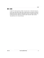
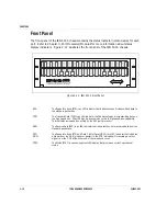
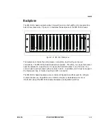
The IEN 4000 is an eight-slot, branch or regional concentrator chassis.  Each IEN 4000 
chassis supports a maximum of eight port processors.  The chassis can be bus connected 
with up to two additional IEN 4000 chassis for a 16, 24, or 32-slot configuration.   

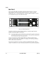
The IEN 4000 chassis uses hot swappable 110/220VAC auto sensing power supplies.  The 
IEN 4000 chassis comes standard with a single power supply and has the option of 
installing a redundant power supply.

The IEN 4000 chassis come standard with a single power supply and a second redundant 
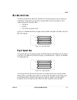
power supply.  When IEN 4000s chassis are bus connected, the standard and high speed 
bus are extended. 

The IEN 4000 chassis allows different technologies to come together on a centrally 
managed platform, including SNA/SDLC, ASYNC, BSC 3270, IP and IPX.  It also integrates 
multiple traffic types over a single WAN interface, such as ISDN, X.25, or frame relay.  The 
IEN 4000 chassis comes with the ability to add an asynchronous transfer mode (ATM) T1 or 
OC3 interface to utilize the performance advances of cell relay.  

Digital or analog voice interfaces can be used to provide compressed or channelized voice 
capability.  Each voice port processor supports four, 2-wire or two, 4-wire voice channels 
per port processor for a maximum of 48 voice channels for each IEN 4000 chassis.

Содержание IEN 1000

Страница 1: ...Hardware Reference Version 1 5 I n t e g r a t e d E n t e r p r i s e N e t w o r k 940043 002 ...

Страница 2: ...stinguish proprietary trademarks from descriptive terms by following the capitalization style used by the manufacturer Every effort has been made to supply complete and accurate information However Hypercom assumes no responsibility for its use nor any infringement of the intellectual property rights of third parties which would result from such use Copyright 1997 by HYPERCOM INC Manufactured in t...

Страница 3: ...elevision reception These devices have been tested and certified to comply with the limits for a Class A digital device as defined in Part 15 of the Federal Communications Commission FCC rules Class A limits are designed to provide reasonable protection against radio television interference in a business environment To comply with FCC regulations you must use shielded cables with these devices Ope...

Страница 4: ......

Страница 5: ...s 1 3 Chapter 5 System Configuration 1 3 Chapter 6 IEN 1000 Configuration 1 3 CHAPTER 2 CHASSIS 2 1 Chassis Specifications 2 3 Safety Precautions 2 4 IEN 1000 2 5 Front Panel 2 6 Rear Panel 2 7 IEN 2000 2 8 Front Panel 2 8 Rear Panel 2 9 IEN 3000 2 10 Front Panel 2 10 Backplane 2 11 Rear Panel 2 12 IEN 4000 2 13 Front Panel 2 14 Rear Panel 2 15 Power Supply 2 16 IEN 5000 2 17 Front Panel 2 18 Back...

Страница 6: ... Line 2 25 10Base T 2 26 Token Ring UTP 2 26 RS485 LAN 2 27 V 35 2 28 V 24 RS232C 2 29 10Base 2 LAN 2 30 Token Ring STP 2 31 RS485 LAN 2 32 CHAPTER 3 PORT PROCESSORS MODULES 3 1 Port Processors 3 3 Physical Interfaces 3 4 CID15H CID15H A 3 6 CID61 3 9 CID61 Dual 3 11 CID63 3 12 CIM15H 33 3 16 DLA14 3 19 DSX11 3 25 DTC11 E1 3 27 DTC11 LHO 3 27 LET61 3 30 LET61B 3 30 LET61H 3 30 LTR61 3 32 ...

Страница 7: ...DLZ10 3 39 DSU63 3 40 DVF18 3 41 HDM14 3 44 HDM28 3 45 ISD01 ST 3 46 ISD01 U 3 47 PCM14 3 48 PCM28 3 49 MEM61 3 50 IEN 1000 3 51 CPA03 3 54 DSU56 3 56 LET10 3 57 LTR10 3 58 HUB08 3 59 MAU08 3 60 IDT10 3 61 CHAPTER 4 CABLE SPECIFICATIONS ADAPTERS 4 1 Introduction 4 3 Selecting Cables 4 4 Cable Types 4 7 Type A 4 7 Type ALG 2W 4 8 Type ALG PD 4 10 ...

Страница 8: ...e RIRO 4 22 Type RJ11 4 23 Type T1 4 24 Type T1K 4 25 Type T1 45 M 4 26 Type T1 15 XF 4 27 Type T1 45 XF 4 28 Type T 63 4 29 Type TR 4 30 Type UET 4 31 Type UTR 45 M 4 32 Type V 4 33 Type VF 4 34 Type VM 4 35 Type VNN 4 37 Type VX 4 38 Type Y 4 39 Type YA 4 41 Type Y 63 4 43 Type 2VE 4 45 HUB08 LET10 PATCH 4 47 Power Cables 4 48 Adapters 4 50 LEC01 4 50 LAU01 4 51 ...

Страница 9: ... Bus Clock Settings 5 6 DIP Switch Settings 5 7 Bus Extension 5 8 High Speed Bus Extension 5 9 IEN 4000 Configuration 5 10 Bus Extension 5 10 High Speed Bus Extension 5 11 IEN 5000 Configuration 5 12 Bus Clock Settings 5 12 DIP Switch Settings 5 13 Bus Extension 5 14 High Speed Bus Extension 5 15 CHAPTER 6 SYSTEM CONFIGURATION 6 1 IEN 1000 Configuration 6 3 Software Configuration 6 4 WAN Port Init...

Страница 10: ...TABLE OF CONTENTS VI IEN HARDWARE REFERENCE 940043 002 ...

Страница 11: ...C H A P T E R 1 Introduction In This Chapter IEN Hardware Reference 1 3 ...

Страница 12: ......

Страница 13: ...00 chassis Chapter 3 Port Processors and Modules This chapter describes the Hypercom port processors and modules It includes block diagrams bus communications and jumper settings Chapter 4 Cables and Adapters This chapter describes the Hypercom solutions for connectivity This chapter includes a cable matrix and detailed specifications on Hypercom cables and adapters Chapter 5 System Configuration ...

Страница 14: ...CHAPTER 1 1 4 IEN HARDWARE REFERENCE 940043 002 ...

Страница 15: ...H A P T E R 2 Chassis In This Chapter Chassis Specifications 2 3 Safety Precautions 2 4 IEN 1000 2 5 IEN 2000 2 8 IEN 3000 2 10 IEN 4000 2 13 IEN 5000 2 17 Bus Architecture 2 21 Chassis Port Pinouts 2 24 ...

Страница 16: ......

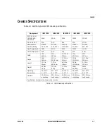
Страница 17: ...W 30W 150W 110W Heat Dissipation DC N A N A N A N A 90W Width 19in 483mm 19in 483mm 10 7 8 in 276mm 17in 432 3mm 19in 483mm Depth 14in 360mm 14 0in 355 61mm 17 3 4in 451mm 12 5in 304 8mm 21 7 8in 556mm Height 1 7 8in 29mm 1 75in 44 46mm 6 1 8in 156mm 5 25in 133 35mm 5 1 8in 130mm Weight 4 25lbs 1 9Kg 15 0lbs 6 7Kg 11 1lbs 5Kg 19lbs 8 486Kg 26lbs 11 8Kg Operating Temperature 32 104 F 0 40 C 32 104 ...

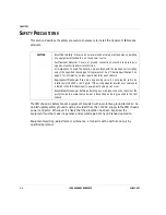
Страница 18: ...afety Observe all normal electrical safety practices when operating any equipment attached to an active power source Authorized Service Covers or ground connections must be removed by a Hypercom authorized service technician Fire Hazard To avoid fire hazard only use fuses with the required current rating and of the specified chassis type for replacement See Chassis Specifications on page 3 for inf...

Страница 19: ... bridge bridge router or access device for a downstream controller or terminal SDLC Bisync Due to its design flexibility the IEN 1000 chassis can have three additional serial ports an Ethernet or Token Ring router port an eight port UTP hub or an eight port Token Ring multiple access unit MAU data compression data encryption integrated DSU and 14 4Kbps dial backup ...

Страница 20: ... and addressing HUB Interface The HUB Interface contains LED indicators for the partition and link status of each port on the HUB08 16 or MAU HUB08 Refer to Chapter 3 LET10 for more information about the Ethernet upgrade module MAU08 Refer to Chapter 3 LTR10 for more information about the Token Ring upgrade module RUN Indicator The RUN Indicator contains an LED which flashes to indicate the CPU is...

Страница 21: ...ections The DBU connections consist of one RJ11 port for a 2 wire modem and one RJ45 port for a 4 wire line interface used with the optional V 32bis DBU Modem This provides a dial backup connection WAN Serial Port 1 Connections The WAN Serial Port 1 connections consist of one DB25 RS232 V 35 WAN port and one DB25 RS232 serial port Optional Serial Ports The Serial Port connections 2 3 and 4 consist...

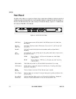
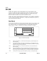
Страница 22: ...Refer to Chapter 3 Port Processors for more information about the status display indicators Figure 2 1 illustrates the front panel of the IEN 2000 chassis Figure 2 3 IEN 2000 Front Panel SBUS TX The Standard Bus Transmit is an LED indicator that indicates the unit is transmitting data to the standard packet bus HiBUS ACT The High Speed Bus Activity is an LED indicator that indicates the port is tr...

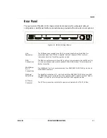
Страница 23: ...ard Token Ring UTP connection There are also two bus expansion ports one labeled IN and one labeled OUT The bus expansion ports are used for interconnecting an IEN 2000 with up to three additional IEN 2000 chassis Up to four IEN 2000 chassis can be bus connected using a Hypercom Type HB2 cable Two chassis are connected by inserting a Type HB2 cable into the OUT port of the first chassis and into t...

Страница 24: ...play indicators Figure 2 5 illustrates the front panel of the IEN 3000 chassis Figure 2 5 IEN 3000 Front Panel RTS The Request to Send RTS is an LED indicator that indicates the unit is transmitting data to the standard packet bus TXD The Transmit Data TXD is an LED indicator that indicates the port is transmitting data on the high speed bus Older Z80 port processors do not have high speed bus cap...

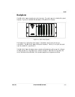
Страница 25: ...ane The backplane contains the port processor connectors bus circuitry and power connections The IEN 3000 chassis backplane is passive That is no one port processor need be installed in a specific slot The IEN 3000 chassis backplane also contains configurations switches used to configure multiple chassis as a single IEN node Refer to Chapter 5 IEN 3000 Configuration for more information about the ...

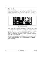
Страница 26: ...s DCE use the appropriate interface adapter cable Refer to Chapter 4 Cable Specifications Adapters for more information about specific cabling parameters The six RJ11 LAN connectors are used only with the Hypercom RS485 terminal LAN The six RJ11 line connectors are used with adapter interfaces or cables to support media in addition to the standard RJ11 dial capability For example UTP Token Ring or...

Страница 27: ... a second redundant power supply When IEN 4000s chassis are bus connected the standard and high speed bus are extended The IEN 4000 chassis allows different technologies to come together on a centrally managed platform including SNA SDLC ASYNC BSC 3270 IP and IPX It also integrates multiple traffic types over a single WAN interface such as ISDN X 25 or frame relay The IEN 4000 chassis comes with t...

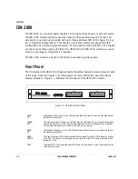
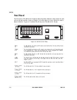
Страница 28: ...d bus capability This indicates low speed bus activity on the Z80 port processor SBUS RX The Standard Bus Receive is an LED indicator that indicates the unit is receiving data from the standard packet bus USER PORTS The User Ports is an LED indicator that indicates a signal from the DCE modem or printer to the DTE indicating it is receiving a carrier signal from the DCE at the other end of the tel...

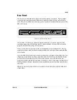
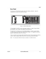
Страница 29: ...such as RS232 V 35 Thinnet or AUI Ethernet and analog voice The eight RJ11 connectors are used with adapter interfaces or cables to support media including analog dial UTP Ethernet DS1 T1 DDS and ISDN The eight RJ45 connectors support a standard Token Ring UTP connection There are also two bus expansion ports labeled IN and OUT The bus expansion ports are used for interconnecting an IEN 4000 with ...

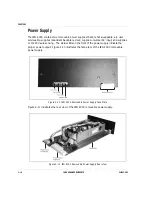
Страница 30: ...s universal AC input and supplies 110 220V auto sensing The status LEDs on the front of the power supply indicate the proper power output Figure 2 10 illustrates the face plate of the IEN 4000 removable power supply Figure 2 10 IEN 4000 Removable Power Supply Face Plate Figure 2 11 illustrates the rear view of the IEN 4000 removable power supply Figure 2 11 IEN 4000 Removable Power Supply Rear Vie...

Страница 31: ... have modules attached do not require an RJ11 port and do not require access to the high speed bus The IEN 5000 chassis is typically used at host or regional sites where port density and scalability are important The IEN 5000 chassis can function as a regional concentrator of feeder nodes As a stand alone unit it can perform as a powerful multiprotocol router The IEN 5000 chassis contains redundan...

Страница 32: ...ansmit Data TXD is an LED indicator that indicates the port is transmitting data on the high speed bus Older Z80 port processors do not have high speed bus capability This indicates low speed bus activity on the Z80 port processor RXD The Receive Data RXD is an LED indicator that indicates the unit is receiving data from the standard packet bus RTS DCD The Request to Send RTS and Data Carrier Dete...

Страница 33: ...ections The IEN 5000 chassis backplane is passive Therefore no one port processor need be installed in a specific slot However the first slot marked C is a thin slot You cannot install a port processor with a module in slot C In addition slot C does not support the high speed bus or media requiring an RJ11 connector The IEN 5000 chassis backplane also contains configuration switches used to config...

Страница 34: ... media in addition to the standard RS232 DTE interface Note When using the DB25 connector for RS232 the connector is DTE To perform as DCE use the appropriate interface adapter cable Refer to Chapter 4 Cable Specifications Adapters for more information about specific cabling parameters The RJ11 connectors are used with adapter interfaces or cables to support media in addition to the standard RJ11 ...

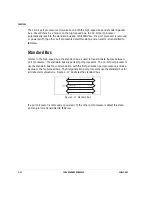
Страница 35: ... and IEN 5000 chassis Figure 2 15 Bus Architecture High Speed Bus The high speed bus is a parallel bus used to transport data frames between the 32 bit port processors The data may contain LAN Legacy or packetized voice Figure 2 16 illustrates the high speed bus Figure 2 16 High Speed Bus The high speed bus is used by the Hypercom second generation port processors LET61 LTR61 CID61 and CID63 port ...

Страница 36: ...ENView Standard Bus Similar to the high speed bus the standard bus is used to transmit data frames between port processors The standard bus supports all port processors The 32 bit port processors use the standard bus for communication with the first generation port processors and as a backup to the high speed bus The first generation port processors use the standard bus for all data communications...

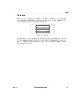
Страница 37: ...DM bus is used for FT1 T1 E1 drop and insert voice and data Figure 2 18 illustrates the TDM bus Figure 2 18 TDM Bus The IEN 2000 IEN 3000 IEN 4000 and IEN 5000 chassis can terminate up to four T1 E1s The TDM bus is accessible by the DTC11 CID61 CID63 and DLA14 port processors Refer to Chapter 3 Port Processors Modules for more information about these and other Hypercom port processors ...

Страница 38: ...essor n Refer to page 2 5 IEN 1000 for more information about the IEN 1000 chassis specifications n Refer to page 2 8 IEN 2000 for more information about the IEN 2000 chassis specifications n Refer to page 2 10 IEN 3000 for more information about the IEN 3000 chassis specifications n Refer to page 2 13 IEN 4000 for more information about the IEN 4000 chassis specifications n Refer to page 2 17 IEN...

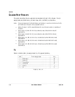
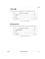
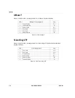
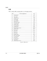
Страница 39: ...Line Table 2 4 lists the RJ11 pin assignments for a dial or leased line physical interface Table 2 4 RJ11 Dial Lease Line PIN 2 Wire E M Pin Assignment Key 1 Signal Battery SB 2 Mouth M 3 Ring R 4 TIP T 5 Telco Ground GND 6 Ear E PIN Dial Lease Line Pin Assignment Key 1 Receive Ring 4 wire only RR 2 Receive TIP 4 wire only RT 3 Ring R 4 TIP T 5 Pin not used N A 6 Pin not used N A ...

Страница 40: ...nts for a Token Ring UTP Unshielded Twisted Pair physical interface Table 2 6 RJ11 Token Ring UTP PIN 10Base T Pin Assignment Key 1 Transmit Positive TX 2 Transmit Negative TX 3 Receive Positive RX 4 Pin not used N A 5 Pin not used N A 6 Receive Negative RX PIN T1 Pin Assignment Key 1 Pin not used N A 2 Pin not used N A 3 Transmit Positive TX 4 Receive Positive RX 5 Receive Negative RX 6 Transmit ...

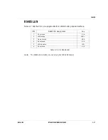
Страница 41: ...11 pin assignments for an RS485 LAN physical interface Table 2 7 RJ11 RS485 LAN Note The RS485 LAN interface is used only by the IEN 3000 chassis PIN RS485 Pin Assignment Key 1 Pin not used N A 2 LAN Positive LAN 3 Frame Ground GND 4 Pin not used N A 5 LAN Negative LAN 6 Pin not used N A ...

Страница 42: ...6 Data Set Ready DSR 7 Signal Ground SG 8 Data Carrier Detect DCD 9 Transmit Clock B TC B 10 Receive Clock B RC B 11 Transmit Data B TD B 12 Receive Data B RD B 13 External Transmit Clock B ETC B 14 Receive Data A RD A 15 Pin not used N A 16 Pin not used N A 17 Pin not used N A 18 Pin not used N A 19 Receive Clock A RC A 20 Data Terminal Ready DTR 21 Transmit Clock A TC A 22 Pin not used N A 23 Tr...

Страница 43: ...232C Pin Assignment Key 1 Frame Ground FG 2 Transmit Data TD 3 Receive Data RD 4 Request To Send RTS 5 Clear To Send CTS 6 Data Set Ready DSR 7 Signal Ground SG 8 Data Carrier Detect DCD 9 Pin not used N A 10 Pin not used N A 11 Pin not used N A 12 Pin not used N A 13 Pin not used N A 14 Pin not used N A 15 Transmit Clock TC 16 Pin not used N A 17 Receive Clock RC 18 Pin not used N A 19 Pin not us...

Страница 44: ...round FG 2 Pin not used N A 3 Pin not used N A 4 Pin not used N A 5 Pin not used N A 6 Pin not used N A 7 Signal Ground SG 8 Pin not used N A 9 Receive Positive RX 10 Positive Five volts 5V 11 Transmit Positive TX 12 Pin not used N A 13 Carrier Detect Positive CD 14 Positive Twelve volts 12V 15 Pin not used N A 16 Pin not used N A 17 Pin not used N A 18 Pin not used N A 19 Pin not used N A 20 Pin ...

Страница 45: ... 3 Pin not used N A 4 Pin not used N A 5 Pin not used N A 6 Transmit Negative TX 7 Ground GND 8 Ground GND 9 Receive Negative RX 10 Pin not used N A 11 Positive Five volts 5V 12 Pin not used N A 13 Pin not used N A 14 Pin not used N A 15 Pin not used N A 16 Pin not used N A 17 Pin not used N A 18 Pin not used N A 19 Transmit Positive TX 20 Ground GND 21 Ground GND 22 Receive Positive RCV 23 Pin no...

Страница 46: ... N A 2 Pin not used N A 3 Pin not used N A 4 Pin not used N A 5 Pin not used N A 6 Pin not used N A 7 Pin not used N A 8 Pin not used N A 9 Pin not used N A 10 Pin not used N A 11 Pin not used N A 12 Pin not used N A 13 Pin not used N A 14 Pin not used N A 15 Pin not used N A 16 LAN Negative LAN 17 Pin not used N A 18 LAN Positive LAN 19 Pin not used N A 20 Pin not used N A 21 Pin not used N A 22 ...

Страница 47: ...C H A P T E R 3 Port Processors Modules In This Chapter Port Processors 3 3 Modules 3 35 IEN 1000 3 51 ...

Страница 48: ......

Страница 49: ... used in modern data communications networks The port processors contain all memory needed to run the CPU independently Figure 3 1 illustrates the port interface architecture Figure 3 1 Port Interface Architecture 32 bit CPU port processors are used for applications requiring very high throughput or for support of specialized functions such as Token Ring LAN interfacing Ports are soft and can oper...

Страница 50: ...f port processors support the following interface technologies n RS232 C n V 35 n DDS 56 64K n Ethernet BNC AUI UTP n T R STP IBM UTP n T1 E1 FT1 n Modem V 34 2 Wire Dial 2 Wire Leased 4 Wire Leased n Analog Voice 2 Wire Loop Start FXO FXS 4 Wire E M n Bus Extension IEEE n RS 485 n ISDN BRI PRI ...

Страница 51: ... low nibble of the bus address and CU address n On Off Reset toggle switch used to enable or disable power to the port processor and to perform a port processor restart after a modification usually address changes is made n One pair of Mode Select DIP switches used to configure the port processor and software n Bus LEDs that provide transmit receive and bus traffic status n Seven segment LED displ...

Страница 52: ... DTE The CID15H A port processor is only capable of V 35 DCE Figure 3 3 illustrates the block diagram for the CID15H port processor Figure 3 3 CID15H Block Diagram Figure 3 4 illustrates the block diagram for the CID15H A port processor Figure 3 4 CID15H A Block Diagram Note The optional DES01 encryption and DLZ01 compression modules may be used on the CID15H port processor with software supportin...

Страница 53: ...RK 3 7 Figure 3 5 illustrates the bus communications for the CID15H CID15H A port processor Figure 3 5 CID15H CID15H A Bus Communications Figure 3 6 illustrates the jumper locations on the CID15H CID15H A port processor Figure 3 6 CID15H CID15H A Jumper Locations ...

Страница 54: ...ed JT2 CPU Clock 8 16MHz 16MHz Pins 2 3 connected JT5 Memory paging 16 32 Do not connect JT17 Modem Output SCC1A SCC2A Do not connect JT18 Modem Monitor Normal On Normal Pins 1 2 connected JT24 Page Memory Enabled Disabled Do not connect JT35 NAC1A Do not connect JT36 NAC1A Do not connect JT37 NAC1A Do not connect JT38 NAC1A Do not connect JT41 Modem Monitor Normal On Normal Pins 1 2 connected JT4...

Страница 55: ...odule for packetized voice Other uses include subrate or channelized legacy protocol termination and clear channel muxing of applications such as video A typical application would be the CID61 port processor configured as a Frame Relay WAN port receiving LAN data from the high speed bus and legacy data from the standard bus The CID61 port processor places the data in a frame relay packet and trans...

Страница 56: ...Diagram Figure 3 9 illustrates the jumper locations for the CID61 port processor Figure 3 9 CID61 Jumper Locations Table 3 2 lists the jumper definitions for the CID61 port processor Table 3 2 CID61 Jumper Definitions JUMPER DESCRIPTION FACTORY SETTING JT7 Battery On Off Battery On Pins 2 3 connected JT11 JT20 V 35 RS232 Left V 35 Right RS232 ...

Страница 57: ...nk connection between a central and regional IEN node Notes 1 The jumper JT11 20 must be in the left position 2 The CID61 Dual port processor requires a type 2VE cable which attaches to the DB25 connector of the appropriate IEN 2000 IEN 3000 IEN 4000 or IEN 5000 chassis port The 2VE cable contains two female DB25 connectors which allow two types of V or VF cables to be attached The purpose of the ...

Страница 58: ...ST ST interface or ISDN BRI interface if ISDN backup is required Note The RS232 and V 35 connections on the CID63 port processor are made through the female DB25 connector on the rear of the chassis using a Type Y 63 cable The end device connections are brought to two DB25 female connectors at the end of the Type Y 63 cable Optional crossover or DB25 to V 35 connector cables are available for conn...

Страница 59: ...13 Figure 3 11 illustrates the bus communications for the CID63 port processor Figure 3 11 CID63 Bus Communications Figure 3 12 illustrates the jumper and expansion module connections on the component side of the CID63 port processor Figure 3 12 CID63 Jumper Locations ...

Страница 60: ...CHAPTER 3 3 14 IEN HARDWARE REFERENCE 940043 002 Figure 3 13 illustrates the block diagram for the CID63 port processor Figure 3 13 CID63 Block Diagram ...

Страница 61: ...0 Second 2 wire Telco line Not Installed CID63 Open IEN 500 Closed JT21 Second 2 wire Telco line Not Installed CID63 Open IEN 500 Closed JT22 Telco Ground Installed CID63 Closed IEN 500 Open JT23 Chassis Ground Not Installed JT24 Telco Ground to Chassis Ground Not Installed CID63 Closed IEN 500 Closed JT25 Second 2 wire Telco line Not Installed CID63 Open IEN 500 Closed JT26 First Telco line conne...

Страница 62: ...33 port processor is capable of all functions performed by the CID15H port processor The addition of the DLZ01 compression module can normally achieve near 56K throughput The CIM15H port processor can be used in a central or remote IEN 2000 IEN 3000 IEN 4000 or IEN 5000 chassis and is also can be used to communicate with the dial backup used in the IEN 1000 chassis Figure 3 14 illustrates the bus ...

Страница 63: ...NTERPRISE NETWORK 3 17 Figure 3 15 illustrates the block diagram for the CIM15 33 port processor Figure 3 15 CIM15 33 Block Diagram Figure 3 16 illustrates the jumper locations for the CIM15H 33 port processor Figure 3 16 CIM15H 33 Jumper Locations ...

Страница 64: ...not connect JT17 Do not connect JT18 Modem Monitor Normal On Normal Pins 1 2 connected JT24 Do not connect JT30 Modem Equalization On Off Equalization Off Pins 1 2 connected JT31 TX 9dbm TX 2dbm TX 9dbm Pins 2 3 connected JT35 Do not connect JT36 Do not connect JT37 Do not connect JT38 Do not connect JT39 Do not connect JT40 Ring Detect Loop Ground Start Loop Start Pins 2 3 connected JT41 Modem Mo...

Страница 65: ...nd Telco connections using E M or loop start signalling In addition an optional ring generator may be installed for use with handsets Figure 3 17 illustrates the bus communications for the DLA14 port processor Figure 3 17 DLA14 Bus Communications Notes 1 Compression to 8Kbps packetized voice can be achieved by using a DLA14 port processor in non ADPCM mode and a CID61 port processor with a IDV01 o...

Страница 66: ...EFERENCE 940043 002 Figure 3 18 illustrates the block diagram for the DLA14 port processor Figure 3 18 DLA14 Block Diagram Figure 3 19 illustrates the jumper locations for the DLA14 port processor Figure 3 19 DLA14 Jumper Locations ...

Страница 67: ...ry 48V Refer to Table 3 6 for the correct jumper settings JT17 Line 2 DC Ring Detect Bypass Enabled Disabled Bypass Enabled Pins 1 2 connected JT18 Line 1 DC Ring Detect Bypass Enabled Disabled Bypass Enabled Pins 1 2 connected JT19 Not Used Not Used JT20 Line 2 E Lead Control System Battery 48V Refer to Table 3 6 for the correct jumper settings JT21 Line 1 E Lead Control System Battery 48V Refer ...

Страница 68: ..._ _ _ _ _ _ _ _ _ _ _ _ _ _ _ _ _ JT13 1 2 2 3 _ _ _ _ _ _ _ 2 3 2 3 2 3 JT16 1 2 2 3 _ _ _ _ _ _ _ 2 3 2 3 2 3 JT17 _ _ _ _ _ _ _ 2 3 _ _ _ _ _ _ _ 1 2 _ _ _ _ _ _ _ _ _ _ _ _ _ _ JT18 _ _ _ _ _ _ _ 2 3 _ _ _ _ _ _ _ 1 2 _ _ _ _ _ _ _ _ _ _ _ _ _ _ JT19 Not Used _ _ _ _ _ _ _ _ _ _ _ _ _ _ _ _ _ _ _ _ _ _ _ _ _ _ _ _ _ _ _ _ _ _ _ JT20 1 2 2 3 1 2 2 3 2 3 2 3 JT21 1 2 2 3 1 2 2 3 2 3 2 3 JT22 Not...

Страница 69: ...ENTERPRISE NETWORK 3 23 The following jumper information are for the DLA14 Version F port processor Figure 3 20 illustrates the jumper and expansion module locations on the DLA14 Version F port processor Figure 3 20 DLA14 Version F Jumper Locations ...

Страница 70: ...ER Type 1 Normal Type 1 Tandem Type 2 Normal Type 2 Tandem Type 5 Normal Type 5 Tandem JT16 Not Used _ _ _ _ _ _ _ _ _ _ _ _ _ _ _ _ _ _ _ _ _ _ _ _ _ _ _ _ _ _ _ _ _ _ _ JT17 Not Used _ _ _ _ _ _ _ _ _ _ _ _ _ _ _ _ _ _ _ _ _ _ _ _ _ _ _ _ _ _ _ _ _ _ _ JT18 Not Used _ _ _ _ _ _ _ _ _ _ _ _ _ _ _ _ _ _ _ _ _ _ _ _ _ _ _ _ _ _ _ _ _ _ _ JT19 Not Used _ _ _ _ _ _ _ _ _ _ _ _ _ _ _ _ _ _ _ _ _ _ _ _...

Страница 71: ...signal The reverse is true when the DSX11 port processor is used to provide master clocking That is the T1 transmit clock is locked to the PCM highway clock In addition the DSX11 port processor contains a 512 channel digital space time switch used for multiplexing and channel control The DSX11 port processor supports ISDN PRI when combined with CID61 port processor for D and B channel termination ...

Страница 72: ...ble 3 8 lists the jumper definitions for the DSX11 port processor Table 3 8 DSX11 Jumper Definitions JUMPER DESCRIPTION FACTORY SETTING JT1 Battery On Off Battery On Pins 2 3 connected JT2 SCC Clock 6 12 19MHz 6MHz Pins 1 2 connected Do not change setting JT3 Do not connect JT4 CPU Clock 6 12MHz 6MHz Pins 1 2 connected Do not change setting JT5 Do not connect ...

Страница 73: ...ocessor supports ISDN PRI when combined with CID61 port processor for D and B channel termination DTC11 LHO The DTC11 LHO port processor Part 030012 002 is a long haul receiver that is typically designed to fully restore a received signal after transmission though a cable with attenuation of either 0 to 26 dB or 0 to 36 dB The smaller range allows for increased noise margin in shorter loop operati...

Страница 74: ...002 Figure 3 24 illustrates the bus communications for the DTC11 LHO E1 port processor Figure 3 24 DTC11 LHO E1 Bus Communications Figure 3 25 illustrates the block diagram for the DTC11 LHO E1 port processor Figure 3 25 DTC11 LHO E1 Block Diagram ...

Страница 75: ...ocations Table 3 9 lists the jumper definitions for the DTC11 LHO E1 port processor Table 3 9 DTC11 LHO E1 Jumper Definitions JUMPER DESCRIPTION FACTORY SETTING JT1 Battery On Off Battery On Pins 2 3 connected JT2 SCC Clock 6 12 19MHz 6MHz Pins 1 2 connected Do not change setting JT3 Do not connect JT4 CPU Clock 6 12MHz 6MHz Pins 1 2 connected Do not change setting JT5 Do not connect ...

Страница 76: ...formance Ethernet interface using a Motorola 68340 CPU The LET61B port processor is used strictly for IEN bus extension or as a bus monitor The LET61B port processor supports 10Base T 10Base 2 using the LEC01 Thinnet Ethernet adapter and AUI using the LAU01 AUI Interface adapter connections LET61H The LET61H port processor Part 030020 002 is a high performance Ethernet interface with a 1MB memory ...

Страница 77: ...1H Block Diagram Figure 3 29 illustrates the jumper location for the LET61 LET61B and LET61H port processors Figure 3 29 LET61 LET61B and LET61H Jumper Locations Table 3 10 lists the jumper definition for the LET61 LET61B and LET61H port processor Table 3 10 LET61 LET61B and LET61H Jumper Descriptions JUMPER DESCRIPTION FACTORY SETTING JT7 Battery Backup On Off Battery On Pins 2 3 connected ...

Страница 78: ...gh performance Token Ring interface using a Motorola 68340 CPU The LTR61B port processor is used strictly for IEN bus extension or as a bus monitor The LTR61B port processor supports STP and UTP connections and 4 to 16Mbps LTR61H The LTR61H port processor Part 030023 002 is a high performance Ethernet interface with a 1MB memory expansion The LET61H port processor is used for routing bridging and ...

Страница 79: ...gure 3 31 illustrates the block diagram for the LTR61 LTR61B and LTR61H port processors Figure 3 31 LTR61 LTR61B and LTR61H Block Diagram Figure 3 32 illustrates the jumper locations for the LTR61 LTR61B and LTR61H port processors Figure 3 32 LTR61 LTR61B and LTR61H Jumpers ...

Страница 80: ...sts the jumper definitions for the LTR61 LTR61B and LTR61H port processors Table 3 11 LTR61 LTR61B and LTR61H Jumper Descriptions JUMPER DESCRIPTION FACTORY SETTING JT7 Battery Backup On Off Battery On Pins 2 3 connected JT9 Chassis Ground to TROLI Do not connect ...

Страница 81: ...gurations CIR01 The CIR01 module Part 030149 001 is a single channel plug in module that provides a single RS232 interface to the CID63 port processor The CIR01 module plugs into the CNEA2 and CNL1 or CNEB2 and CNL2 sockets on the CID63 port processor Figure 3 33 illustrates the front and back side of the CIR01 module Figure 3 33 CIR01 Module ...

Страница 82: ... a single channel plug in module that creates a single V 35 interface to the CID63 port processor The CIV01 module plugs into the CNEA2 and CNL1 or CNEB2 and CNL2 sockets on the CID63 port processor Figure 3 34 illustrates the front and back side of the CIV01 module Figure 3 34 CIV01 Module ...

Страница 83: ...o the CNS1 A and B sockets on the CID61 port processor the CNEA2 and CNL1 or CNEB2 and CNL2 sockets on the CID63 port processor or CNS2 A and B sockets in the IEN 1000 chassis Figure 3 35 illustrates the front and back side of the DES10 module Figure 3 35 DES10 Module Note The installation of the DES10 module does not enable encryption The IENView software is required to load the key into the cent...

Страница 84: ...e CID15H CID15H A and CIM15H 33 port processors The compression module replaces the Z80 CPU on the port processor in use An average 3 1 or 4 1 compression is normal and is frequently used with 14 4 dial backup to achieve near 56K performance Figure 3 36 illustrates the front and back of the DLZ01 C module Figure 3 36 DLZ01 C Module ...

Страница 85: ...and the IEN 1000 chassis The DLZ10 module plugs into the CNS1 A and B sockets on the CID61 port processor the CNEA2 and CNL1 or CNEB2 and CNL2 sockets on the CID63 port processor or CNS2 A and B sockets in the IEN 1000 chassis The DLZ10 module averages between 3 1 and 4 1 compression which is dependent on the data being transferred Figure 3 37 illustrates the front and back side of the DLZ10 modul...

Страница 86: ...bps for the CID63 port processor The DSU63 module plugs into the Expansion Card A sockets CNEA1 CNEA2 CNEA3 and CNEA4 on the CID63 port processor Figure 3 38 illustrates the front and back side of the DSU63 module Figure 3 38 DSU63 Module Note The DSU63 module can only be placed on the front mounting location of the CID63 port processor ...

Страница 87: ... the CID61 port processor The DVF08 18 module plugs into the J1 J3 and J2 sockets of the CID61 port processor In a node requiring only eight voice channels the DVF08 18 module can be placed on the WAN interface Configurations requiring more than eight voice channels are configured with each DVF08 18 residing on its own CID61 port processor The DVF08 18 uses a vocoder for each channel which is capa...

Страница 88: ...eight channel capacity permits the DVF08 18 to support two DLA14 port processors terminating four 4 wire analog voice or two DLA14s terminating eight 2 wire analog voice When used with the DTC11 T1 interface three DVF08 18 CID61s may be combined to support the 24 DS0s from the T1 Figure 3 39 illustrates the front of the DVF08 18 2 module Figure 3 39 DVF08 18 2 Module Front ...

Страница 89: ...3 002 INTEGRATED ENTERPRISE NETWORK 3 43 Figure 3 40 illustrates the front of the DVF08 18 4 module Figure 3 40 DVF08 18 4 Module Front Figure 3 41 illustrates the front of the DVF08 18 8 module Figure 3 41 DVF08 18 8 Module Front ...

Страница 90: ... processor The HDM14 module plugs into the Expansion Card A sockets CNEA1 CNEA2 CNEA3 and CNEA4 or Expansion Card B sockets CNEB1 CNEB2 CNEB3 and CNEB4 on the CID63 port processor In Expansion A of the CID63 the two or four wire option is provided Expansion B is strictly two wire Figure 3 42 illustrates the front and back side of the HDM14 module Figure 3 42 HDM14 Module ...

Страница 91: ...2 CNEA3 and CNEA4 or Expansion Card B sockets CNEB1 CNEB2 CNEB3 and CNEB4 on the CID63 port processor In expansion A of the CID63 port processor the two or four wire option is provided Expansion B is strictly two wire Figure 3 43 illustrates the front and back side of the HDM28 module Figure 3 43 HDM28 Module Note There is a physical difference between the HDM14 and the HDM28 module The HDM28 modu...

Страница 92: ...ID63 port processor The ISD01 ST module plugs into the Expansion Card A sockets CNEA1 CNEA2 CNEA3 and CNEA4 or Expansion Card B sockets CNEB1 CNEB2 CNEB3 and CNEB4 on the CID63 port processor Figure 3 44 illustrates the front and back of the ISD01 ST module Note The ISD01 ST can only be installed in the first port Figure 3 44 ISD01 ST Module ...

Страница 93: ... single ISDN BRI U interface to the CID63 port processor The ISD01 U module plugs into the Expansion Card A sockets CNEA1 CNEA2 CNEA3 and CNEA4 or Expansion Card B sockets CNEB1 CNEB2 CNEB3 and CNEB4 on the CID63 port processor Figure 3 45 illustrates the front and back side of the ISD01 U module Figure 3 45 ISD01 U Module ...

Страница 94: ...is used with the CID63 port processor The functionality of this module is to provide dial backup The PCM14 module can be installed in Expansion Card A sockets CNEA1 CNEA2 CNEA3 and CNEA4 or Expansion Card B sockets CNEB1 CNEB2 CNEB3 and CNEB4 on the CID63 port processor Figure 3 46 illustrates the front and back of the PCM14 module Figure 3 46 PCM14 Module ...

Страница 95: ...or E1 and is used with the CID63 port processor The functionality of this module is to provide dial backup The PCM28 module can be installed in Expansion Card A sockets CNEA1 CNEA2 CNEA3 and CNEA4 or Expansion Card B sockets CNEB1 CNEB2 CNEB3 and CNEB4 on the CID63 port processor Figure 3 47 illustrates the front and back of the PCM28 module Figure 3 47 PCM28 Module ...

Страница 96: ...nd B sockets on the LET61 or LTR61 port processor CNS1 A and B sockets on the CID61 port processsor CNEA2 and CNL1 or CNEB2 and CNL2 sockets on the CID63 port processor or CNS2 A and B sockets in the IEN 1000 chassis The MEM61 is also required with router interfaces LET10 11 and LTR10 11 Figure 3 48 illustrates the component sides of the MEM61 memory upgrade module Figure 3 48 MEM61 Memory Upgrade...

Страница 97: ...ccomplished through the integration of optional upgrade modules Figure 3 49 illustrates the IEN 1000 block diagram Figure 3 49 IEN 1000 Block Diagram The protocol priority algorithm provides allocation of WAN resources for different LAN and legacy protocols High priority traffic queues ensure timely delivery of time sensitive protocols The protocol priority system not only identifies high priority...

Страница 98: ...le to male RS232 cable used to attach the IEN 1000 to external devices n Type VX cross cable used to provide V 35 DCE male interface from the IEN 1000 n Type V adapter cable used to provide V 35 DTE male interface from the IEN 1000 n Type VF adapter cable used to provide V 35 DTE female interface from the IEN 1000 RS232 Port 1 RS232 V 24 56 Kbps Max DTE interface Protocols SDLC SNA SDLC SDLC group...

Страница 99: ...upgrade modules are mutually exclusive For example you can install either the Token Ring interface or the Ethernet interface 2 Refer to Chapter 4 Cable Specifications Adapters for more information about these and other Hypercom cables V 22bis Port One RJ11 and one RJ45 port Cables n RJ11 straight cable used for 2 wire dial up configuration n RJ45 straight cable used for 4 wire dial up configuratio...

Страница 100: ...le Part 030031 001 provides one RS232 V 35 and two RS232 serial port interfaces The CPA03 module is installed only in the IEN 1000 chassis Each port is capable of running a different protocol Figure 3 50 illustrates both sides of the CPA03 module Figure 3 50 CPA03 Module ...

Страница 101: ...V 24 ports Protocols SDLC SNA SDLC SDLC group poll full duplex SDLC to LLC2 conversion X 25 BSC 3270 and BSC 2780 3780 Burroughs Poll Select ASYNC X 3 PAD X 28 Cables n Type D cross cable used to provide RS232 DCE female interface from IEN 1000 n Type A straight male to male RS232 cable used to attach the IEN 1000 to external devices n Type VX cross cable used to provide V 35 DCE male interface fr...

Страница 102: ...ustrates the DSU56 module installed in the IEN 1000 chassis Figure 3 51 Installed DSU56 Module Note The RS232 V 35 WAN port is disabled when the DSU is enabled Table 3 16 lists the interface specifications for the DSU56 module Table 3 16 DSU56 Interface Specifications Note Refer to Chapter 4 Cable Specifications Adapters for more information about the RJ45 straight cable DSU56 One RJ45 port Cables...

Страница 103: ... 3 52 Installed LET10 Module Note The Ethernet and Token Ring interfaces are mutually exclusive Table 3 18 lists the interface specifications for the LET10 module Table 3 17 LET10 Interface Specifications Note Refer to Chapter 4 Cable Specifications Adapters for more information about these and other Hypercom cables LET10 One BNC one AUI and one UTP port Protocols IP IPX Bridging Translational bri...

Страница 104: ...te The Ethernet and Token Ring interfaces are mutually exclusive Table 3 18 lists the interface specification for the LTR10 module Table 3 18 LTR10 Interface Specifications Note Refer to Chapter 4 Cable Specifications Adapters for more information about these and other Hypercom cables LTR10 One STP and one UTP port Protocols IP IPX Bridging SRB RIP RIP2 OSPF Cables n Type IBM adapter cable used to...

Страница 105: ...he LET10 belong to the HUB08 The LET10 router defaults to the UTP port for network access The LET10 UTP port must be connected to one of the eight RJ45 hub ports Hypercom provides an RJ45 straight cable for use with the HUB08 and LET10 upgrade modules Table 3 19 lists the interface specifications for the HUB08 module Table 3 19 HUB08 Interface Specifications Notes 1 The RJ45 straight cable is incl...

Страница 106: ...ides an eight port manageable UTP MUA The Ring In Ring Out RI RO of the MAU08 is accessed using the HUB expansion port on the IEN 1000 using an RIRO cable Figure 3 55 illustrates the interface connections for the MAU08 module Figure 3 55 MAU08 Module Note The LTR10 may not be used with the MAU08 The LTR11 must be used ...

Страница 107: ...e IDT10 module Part 030084 001 is a small module with an RJ45 that plugs into the IEN 1000 motherboard when a DSU is installed The ITD10 is an RJ45 jack and a protective circuitry that allows access to the optional DSU The ITD10 is provided with each DSU Figure 3 56 IDT10 Module ...

Страница 108: ...CHAPTER 3 3 62 IEN HARDWARE REFERENCE 940043 002 ...

Страница 109: ...C H A P T E R 4 Cable Specifications Adapters In This Chapter Introduction 4 3 Selecting Cables 4 4 Cable Types 4 7 Power Cables 4 51 Adapters 4 53 ...

Страница 110: ......

Страница 111: ...nnection pin description and identifies the type of connector used In addition a sample configuration is provided to help you correctly attach the specific cable to the appropriate IEN chassis connector The connection on the back of each IEN chassis corresponds to a port processor The IEN 1000 connections depend upon whether your network specifications require use an optional upgrade module See Ch...

Страница 112: ...ad across the top row to locate the desired physical interface 3 The intersecting cell between the port processor or chassis and physical inter face contains a cable reference letter Note If a cell does not contain a cable designation letter your configuration is not correct Repeat the process starting with Step 1 4 Read down the Cable Reference column until you locate the cable designation refere...

Страница 113: ...Down D Type B IEEE Bus Cable CID61 W A F AA Z U V Y G E Type D RS232 Cross F Type D6 RS232 Cross CID61 Dual U V CC G Type DDS DSU connection H Type HB2 Backplane CID63 A E U V Y BB G Q K I I Type ISDN J Type P PC Connection CIM15H 22B A E K K Type RJ11 L Type T1 RJ11 DB15 CSU CIM15H 33 A E K M Type T1 K RJ11 DB15 CSU N Type T1 45 M RJ45 T1 interface DLA14 B C O Type T1 15 XF 15 pin PBX P Type T1 4...

Страница 114: ...f TYPE P O R T P R O C E S S O R BASE UNIT A B C D F E A Type A Straight RS232 B Type D RS232 Cross CPA03 A B C D F C Type V V 35 DTE male D Type VF V 35 to DCE Dial Backup G E Type VNN F Type VX V 35 DCE Cross DSU56 DSU01 H G Type RJ11 Straight H Type RJ45 Straight HUB08 H J Type RIRO Ring In Ring Out K Type TR1 LET10 H L HUB08 LET10 Patch LTR10 K H MAU08 H Hypercom does not provide cabling for t...

Страница 115: ...com cable that are currently available Type A The Hypercom Type A cable 810009 001 is a male DB25 to male DB25 straight through RS232 cable The cable is used to connect an IEN device to a user device The length of the cable is 10 Figure 4 1 illustrates the pinout for the Type A cable Figure 4 1 Type A Cable Pinouts ...

Страница 116: ...d to connect an IEN RS232C DTE port to an RS232C DCE port The cable is also used with the Hypercom Type D cross cable to enable the IEN device to appear as a DCE device Figure 4 2 illustrates the IEN device setup as a DCE and DTE device Figure 4 2 IEN Device as DCE and DTE ...

Страница 117: ...sets or PBX termination using female RJ11 modular connectors The length of the cable is 3 Figure 4 3 illustrates the pinout for the Type ALG 2W cable Figure 4 3 Type ALG 2W Cable Pinout The Type ALG 2W male DB25 connector is attached to the appropriate line port on the IEN 2000 IEN 3000 IEN 4000 or IEN 5000 chassis that corresponds to the slot containing the DLA14 port processor The Type ALG 2W fe...

Страница 118: ...CHAPTER 4 4 10 IEN HARDWARE REFERENCE 940043 002 Figure 4 4 illustrates the cable connection for the Type ALG 2W cable Figure 4 4 Type ALG 2W Cable Connection ...

Страница 119: ...25 to punch down cable The cable is used to connect a DLA14 port processor to a PBX using a punch down block termination The cable provides four 2 wire or two 4 wire analog voice terminations including E M signalling leads Figure 4 5 illustrates the pinout for the Type ALG PD four two wire cable Figure 4 5 Type ALG PD Four 2 Wire Cable Pinout ...

Страница 120: ...CHAPTER 4 4 12 IEN HARDWARE REFERENCE 940043 002 Figure 4 8 illustrates the cable connection for the Type ALG PD four 2 wire cable Figure 4 6 Type ALG PD Cable Connection Four 2 Wire ...

Страница 121: ...ns the DLA14 port processor The cable is then punched down to an 66 Block using the color codes in the Figure below to identify the correct connections to a PBX Figure 4 5 illustrates the pinout for the Type ALG PD two 4 wire cable Figure 4 7 Type ALG PD Two 4 Wire Cable Pinout Figure 4 8 illustrates the cable connection for the Type ALG PD two 4 wire cable Figure 4 8 Type ALG PD Cable Connection ...

Страница 122: ...us extension cable This cable is a modified IEEE488 cable used to connect two or three IEN chassis at the bus extension port The cable only extends the standard bus Pins 1 2 11 and 23 are removed The length of the cable is 3 5 Figure 4 9 illustrates the pinout for the Type B cable Figure 4 9 Type B Cable Pinouts ...

Страница 123: ... and redundant chassis require terminators attached to the Type B cable connectors Figure 4 10 illustrates the two chassis bus extension termination Figure 4 10 Chassis Bus Extension Termination The Type B cable can be piggybacked to connect three IEN 3000 or IEN 5000 chassis The slave chassis does not require a terminator Figure 4 11 illustrates the three chassis bus extension termination Figure ...

Страница 124: ...10012 001 is a male DB25 to female DB25 cross cable The Type D cable is used with a Type A cable as a DCE connection to a DTE device The IEN chassis provides clocking The length of the cable is 1 Figure 4 12 illustrates the pinout for the Type D cable Figure 4 12 Type D Cable Pinouts ...

Страница 125: ...Type D male DB25 connector is attached to the appropriate port of an IEN 1000 IEN 2000 IEN 3000 IEN 4000 or IEN 5000 chassis The Type D female DB25 connector attaches to the Type A male DB25 connector Figure 4 13 illustrates the use of the Type D cable Figure 4 13 IEN Device as DCE ...

Страница 126: ...ale DB25 to female DB25 cross cable The cable is used only with a CID61 port processor and with a Type A cable as a DCE connection to a DTE device The DTE equipment provides clocking The length of the cable is 1 Figure 4 14 illustrates the pinout for the Type D6 cable Figure 4 14 Type D6 Cable Pinouts ...

Страница 127: ...he Type D6 male DB25 connector is attached to the appropriate port of an IEN 2000 IEN 3000 IEN 4000 or IEN 5000 chassis The Type D6 female DB25 connector attaches to the Type A male DB25 connector Figure 4 15 illustrates the use of the Type D6 cable Figure 4 15 IEN Device as DCE ...

Страница 128: ...strates the pinout for the Type DDS cable Figure 4 16 Type DDS Cable Pinouts The Type DDS male RJ11 connector is attached to an IEN 2000 IEN 3000 IEN 4000 or IEN 5000 chassis port that corresponds to the slot occupied by the CID61 or CID63 port processor When using the Type DDS cable with a CID63 port processor the Type T 63 cable is required The male RJ45 connector is attached to the Telco connec...

Страница 129: ... is 8 Figure 4 18 illustrates the Type HB2 cable Figure 4 18 Type HB2 Cable Note Cable pinout information for the Type HB2 cable is not available One end of the Type HB2 cable must be plugged into the Bus OUT port of an IEN 2000 or IEN 4000 chassis The other end must be plugged into the Bus IN port of the additional IEN 2000 or IEN 4000 chassis Figure 4 19 illustrates the cable connection for the ...

Страница 130: ...4 18 illustrates the Type HB3 cable Figure 4 20 Type HB3 Cable Note Cable pinout information for the Type HB3 cable is not available One end of the Type HB3 cable must be plugged into the Bus OUT port of an IEN 2000 or IEN 4000 chassis The other end must be plugged into the Bus IN port of the additional IEN 2000 or IEN 4000 chassis Figure 4 19 illustrates the cable connection for the Type HB3 cabl...

Страница 131: ...is 10 Figure 4 22 illustrates the pinout for the Type ISDN cable Figure 4 22 Type ISDN Cable Pinout The Type ISDN male RJ45 connector plugs into the line port on the IEN 2000 IEN 3000 IEN 4000 or IEN 5000 chassis The Type ISDN male RJ45 connector is connected to the Network Terminator The Type T 63 cable can be used with the Type ISDN cable Figure 4 23 illustrates the cable connection for the Type...

Страница 132: ... processor at the IEN Node The length of the cable is 10 Figure 4 24 illustrates the pinout for the Type P cable Figure 4 24 Type P Cable Pinouts The Type P male DB25 connector is attached to an IEN 2000 IEN 3000 IEN 4000 or IEN 5000 chassis port that corresponds to the slot occupied by the CID15H port processor The DB9 connector is attached to a PC COM port Figure 4 25 illustrates the use of a Ty...

Страница 133: ...4 26 illustrates the Hypercom Type RIRO cable pin connections and pin descriptions and identifies the cable connectors Figure 4 26 Type RIRO Cable The Type RIRO male DB15 connector is attached to an IEN 1000 HUB expansion port The Type RIRO female RJ45 connectors are plugged into Ring In and Ring Out of a Token Ring Figure 4 27 illustrates the use of the Type RIRO cable Figure 4 27 Type RIRO Cable...

Страница 134: ...wire DLA14 port processor The length of the cable is 1 for 001 and 10 for 002 Figure 4 28 illustrates the pinout for the Type RJ11 cable Figure 4 28 Type RJ11 Cable Pinout The Type RJ11 male connector is plugged into the back of the IEN chassis The other RJ11 male connector is plugged into the ISDN jack The Type RJ11 is also used for DBU connections Figure 4 29 illustrates the cable connection for...

Страница 135: ...or the Type T1 cable Figure 4 30 Type T1 Cable Pinouts Note Some CSU pinouts may differ Refer to the CSU documentation for the DB15 pinout designations The Type T1 male RJ11 connector is attached to the RJ11 port on an IEN 2000 IEN 3000 IEN 4000 or IEN 5000 chassis that corresponds to the slot occupied by the DSX11 or DTC11 LHO port processor The Type T1 male DB15 connector is attached to a CSU Fi...

Страница 136: ...pe T1K cable Figure 4 32 Type T1K Cable Note Some CSU pinouts may differ Refer to the CSU documentation for the DB15 pinout designations The Type T1K male RJ11 connector is attached to the appropriate line port on an IEN 2000 IEN 3000 IEN 4000 or IEN 5000 chassis that corresponds to the slot containing the DSX11 or DTC11 LHO port processors The Type T1K male DB15 connector is plugged into the Kent...

Страница 137: ...ation The length of the cable is 15 Figure 4 34 illustrates the pinout for the Type T1 45 M cable Figure 4 34 Type T1 45 M Cable Pinouts The Type T1 45 M male RJ11 connector is attached to the appropriate line port on the IEN 2000 IEN 3000 IEN 4000 or IEN 5000 chassis that corresponds to the slot containing the DSX11 or DTC11 LHO port processors The Type T1 45 M male RJ45 connector is attached to ...

Страница 138: ...Type T1 15 XF cable Figure 4 36 Type T1 15 XF Cable Pinout The Type T1 15 XF male RJ11 connector attaches to the line port on the IEN 2000 IEN 3000 IEN 4000 or IEN 5000 chassis that corresponds to the slot containing the DSX11 or DTC11 LHO port processors The Type T1 15 XF female DB15 connector is attached to the male DB15 T1 termination from a PBX Telco RJ45 termination Note The Type T1 15 XF cab...

Страница 139: ... the Type T1 45 XF cable Figure 4 38 Type T1 45 XF Cable Pinout The Type T1 45 XF male RJ11 connector attaches to the line port on the IEN 2000 IEN 3000 IEN 4000 or IEN 5000 chassis that corresponds to the slot containing the DSX11 or DTC11 LHO port processor The Type T1 45 XF female RJ45 connector is attached to the male RJ45 T1 termination from a PBX Figure 4 39 illustrates the cable connection ...

Страница 140: ...or This cable can be connected to other Hypercom RJ11 type cables The cable splits out the two line ports of a CID63 port processor The length of the cable is 3 Figure 4 32 illustrates the pinout for the Type T 63 cable Note The second connector only supports a two wire connection Figure 4 40 Type T 63 Cable Pinout Figure 4 41 illustrates the cable connection for the Type T 63 cable Figure 4 41 Ty...

Страница 141: ... of the cable is 10 Figure 4 42 illustrates the pinout for the Type TR cable Figure 4 42 Type TR Cable Pinouts The Type TR cable is used to provide a standard Token Ring STP connection The Type TR male DB25 connector is attached to the appropriate line port of an IEN 2000 IEN 3000 IEN 4000 or IEN 5000 chassis The STP data connector is attached to an STP MAU Figure 4 43 illustrates the cable connec...

Страница 142: ...priate line port of an IEN 2000 IEN 3000 IEN 4000 or IEN 5000 chassis that corresponds the slot containing the LET61 port processor The Type UET male RJ45 connector is then plugged into the appropriate female RJ45 UTP hub port Figure 4 45 illustrates the use of the Type UET Cable Figure 4 45 Type UET Cable Notes 1 The Type UET cable must be attached to an RJ11 line port on the IEN 3000 Do not atta...

Страница 143: ...EN 4000 or IEN 5000 chassis that corresponds with the slot containing the LTR61 port processor The Type UTR male RJ45 connector is attached to a UTP MAU Figure 4 47 illustrates the use of the Type UTR 45 M cable Figure 4 47 Type UTR 45 M Cable Notes 1 The Type UTR 45 M cable must be attached to an RJ11 line port on the IEN 3000 Do not attach the Type UTR 45 M cable to the RJ11 LAN port 2 Do not us...

Страница 144: ...ength of the cable is 10 Figure 4 48 illustrates the pinout for the Type V cable Figure 4 48 Type V Cable Pinouts The Type V male DB25 connector is attached to the appropriate port of an IEN 1000 IEN 2000 IEN 3000 IEN 4000 or IEN 5000 chassis The Type V male V 35 connector is attached to a V 35 DCE serial device Figure 4 49 illustrates the use of the Hypercom Type V cable Figure 4 49 Type V Cable ...

Страница 145: ...e V 35 connector The length of the cable is 10 Figure 4 50 illustrates the pinout for the Type VF cable Figure 4 50 Type VF Cable Pinouts The Type VF male DB25 connector is attached to the appropriate port of an IEN 1000 IEN 2000 IEN 3000 IEN 4000 or IEN 5000 chassis The Type VF female V 35 connector is attached to a male V 35 DCE serial device or cable Figure 4 51 illustrates the use of the Type ...

Страница 146: ...DCE user device The V 35 interface is identical to Hypercom s Type V cable and is typically connects to an external DSU or CSU The RS232 IENView interface is for an asynchronous connection to an external modem for IENView dialup or a direct IENView connection when used with a Type P cable The length of both cables are 10 Figure 4 54 illustrates the pinout for the Type VM cable Figure 4 52 Type VM ...

Страница 147: ...e V 35 connector is attached to a V 35 serial device The Type VM RS232 connector is attached to an RS232 asynchronous modem or cross cable to an IENView PC Figure 4 55 illustrates the cable connections for the Type VM cable Figure 4 53 Type VM Cable Connections Note A female gender changer is required to attach the male DB25 connector of the Type VM to the male DB25 connector of the Type P cable ...

Страница 148: ...illustrates the pinout for the Type VNN cable Figure 4 54 Type VNN Cable Pinouts The Type VNN male DB25 connector marked as DCE must be attached to the IEN 1000 IEN 2000 IEN 3000 IEN 4000 or IEN 5000 chassis port that corresponds to the slot providing the clock The Type VNN male DB25 connector marked as DTE is attached to the desired chassis line port corresponding to the slot configured as the sl...

Страница 149: ...3 or CID15HA port processors provide a clock to the DTE The length of the cable is 10 Figure 4 56 illustrates the pinout for the Type VX cable Figure 4 56 Type VX Cable Pinouts The Type VX male DB25 connector is attached to the appropriate line port of an IEN 1000 IEN 2000 IEN 3000 IEN 4000 or IEN 5000 chassis The Type VX female V 35 connector is attached to a V 35 DTE serial device Figure 4 57 il...

Страница 150: ...021 001 is a male DB25 to three female DB25 cable The cable is used to connect a CID61 port processor to three RS232 DTE ports The CID61 port processor provides clocking The length of the cable is 3 Figure 4 58 illustrates the pinout for the Type Y cable Figure 4 58 Type Y Cable Pinouts ...

Страница 151: ...CABLE SPECIFICATIONS ADAPTERS 940043 002 INTEGRATED ENTERPRISE NETWORK 4 43 Figure 4 59 illustrates the use of the Type Y cable Figure 4 59 Type Y Cable ...

Страница 152: ...com Type YA cable 810025 001 is a male DB25 to three female DB25 cable The cable is used to connect a CID61 port processor to three RS232 DCE ports The length of the cable is 3 Figure 4 60 illustrates the pinout for the Type YA cable Figure 4 60 Type YA Cable Pinouts ...

Страница 153: ...CABLE SPECIFICATIONS ADAPTERS 940043 002 INTEGRATED ENTERPRISE NETWORK 4 45 Figure 4 61 illustrates the use of the Type YA cable Figure 4 61 Type YA Cable ...

Страница 154: ... male DB25 to two female DB25 cable The cable provides two DB25 DTE connectors that come off of a CID63 port processor The length of the cable is 3 This cable can be connected to the Type V VF VX A and D cables Figure 4 64 illustrates the pinout for the Type Y 63 cable Figure 4 62 Type Y 63 Cable Pinout ...

Страница 155: ...NETWORK 4 47 Figure 4 65 illustrates the cable connections for the Type Y 63 cable Figure 4 63 Type Y 63 Cable Connection There is a set of switches on the Type Y 63 cable DB25 connectors for the CID63 port that must be set to the appropriate RS232 or V 35 settings ...

Страница 156: ... 2VE cable 810083 001 is a male DB25 to two female DB25 cable The cable is used only with the CID61 Dual port processor to connect up to two V 35 DCE ports The length of the cable is 3 Figure 4 64 illustrates the pinout for the Type 2VE cable Figure 4 64 Type 2VE Cable Pinouts ...

Страница 157: ...ched to an IEN 2000 IEN 3000 IEN 4000 or IEN 5000 chassis port that corresponds to the slot occupied by the CID61 Dual port processor Each female DB25 connector requires a Type V or VF cable which is then attached to the V 35 DCE device Figure 4 65 illustrates the use of the Type 2VE cable Figure 4 65 Type 2VE Cable ...

Страница 158: ...ation the AUI and BNC port of the LET10 belong to the HUB08 The LET10 router defaults to the UTP port for network access The LET10 UTP port must be plugged into the eight RJ45 hub ports Hypercom provides an RJ45 straight cable for use with the HUB08 and LET10 modules Figure 4 66 illustrates the HUB08 and LET10 module combination using the patch cable Figure 4 66 HUB08 and LET10 Combination Patch C...

Страница 159: ...rovided with either an AC or DC power supply The IEC 320 C14 power input module on each IEN node is labeled 110V 220V or 48V DC Figure 4 67 illustrates the 120VAC power connections for the IEN chassis Figure 4 67 AC 120V Power Cable Figure 4 68 illustrates the IEN 1000 AC power connector Figure 4 68 AC 120V IEN 1000 ...

Страница 160: ...RE REFERENCE 940043 002 The IEC 320 C14 DC connector on an IEN node is modified to prevent the insertion of an AC line cord Figure 4 69 illustrates the 48VDC power connections for the IEN chassis Figure 4 69 DC 48V Power Cable ...

Страница 161: ...ace is required LEC01 The LEC01 030017 001 is a DB25 to Thinnet Ethernet adapter and is used with the LET61 when connecting to a Thinnet cable The LEC01 provides a standard 10Base 2 BNC interface Figure 4 70 illustrates the block diagram for the LEC01 Ethernet Adapter Figure 4 70 LEC01 Block Diagram Figure 4 71 illustrates the LEC01 Ethernet Adapter Figure 4 71 LEC01 Ethernet Adapter ...

Страница 162: ...RDWARE REFERENCE 940043 002 LAU01 The LAU01 TBD is a DB25 to AUI Interface adapter and is used with the LET61 when connecting an AUI interface is required Figure 4 72 illustrates the LAU01 adapter Figure 4 72 LAU01 Adapter ...

Страница 163: ...r To provide additional surge protection for the IEN chassis network access DTC11 LHO port processor an external surge protector is required on each IEN chassis Install only one surge protector per IEN chassis Figure 4 73 illustrates the IEN T1 PCM Line Filter Figure 4 73 IEN T1 PCM Line Filter ...

Страница 164: ...CHAPTER 4 4 56 IEN HARDWARE REFERENCE 940043 002 ...

Страница 165: ...C H A P T E R 5 System Configuration In This Chapter Bus Extension 5 3 IEN 2000 Configuration 5 4 IEN 3000 Configuration 5 6 IEN 4000 Configuration 5 10 IEN 5000 Configuration 5 12 ...

Страница 166: ......

Страница 167: ...ed the number of slots provided by a single chassis you use the bus extension to combine several chassis up to 240 ports into a single IEN logical node Bus connected chassis appear to IENView as a single node with many ports There are two types of bus extensions supported by the IEN 2000 IEN 3000 IEN 4000 and IEN 5000 chassis standard and high speed Note The IEN 1000 chassis does not support bus e...

Страница 168: ...n is not an option with the IEN 2000 chassis The Ethernet or Token Ring bus extension uses LET61B or LTR61B LAN boards respectively however these interfaces may not be used as router interfaces and must have their own dedicated LAN for bus traffic This method extends both the standard and high speed busses n Used when exceeding four chassis n This method of bus expansion is used to extend both the...

Страница 169: ...eed four chassis per node The standard bus is also extended by grouping three chassis using the Hypercom Type HB2 cable and connecting these groups using the Ethernet or Token Ring bus extension Refer to CHAPTER 4 Type HB2 for more information about the Hypercom Type HB2 cable Figure 5 10 illustrates the Ethernet high speed bus extension Figure 5 2 Ethernet High Speed Bus Extension Note The TDM bu...

Страница 170: ... the IEN 3000 chassis backplane Therefore when bus expanding IEN 3000 chassis it is necessary to adhere to the following bus setting Figure 5 3 illustrates the bus clock settings for the IEN 3000 chassis Figure 5 3 IEN 3000 Bus Clock Settings Note The standard bus speed must be set to A factory default when using a standard bus extension If 32 Bit port processors are in use CID61 LET61 LTR61 or CI...

Страница 171: ...ck default factory settings and the other must be set to Redundant Clock If the Master Clock fails the redundant clock takes over Figure 5 4 illustrates the DIP switch settings for the IEN 3000 chassis Figure 5 4 IEN 3000 DIP Switch Settings Note The Master and Redundant chassis are end points of the expanded bus and require bus terminators attached to the Type B cables Refer to CHAPTER 4 Type B f...

Страница 172: ...the standard bus The Ethernet or Token Ring bus extension uses LET61B or LTR61B LAN port processors respectively however these interfaces may not be used as router interfaces and must have their own dedicated LAN for bus traffic This method extends both the standard and high speed busses n Used when exceeding three chassis n This method of bus extension is used to extend both the high speed and th...

Страница 173: ...nd may use 10Base T or 10Base 2 10Base T requires an external UTP HUB 10Base 2 requires an LEC01 for each LET61B and appropriate coax cable The Token Ring bus extension uses the LET61B port processor and requires a UTP or STP MAU Refer to CHAPTER 3 Port Processors Modules for more information about the LET61B and LTR61B port processors Note The Ethernet or Token Ring extended bus must not be share...

Страница 174: ... standard bus extension may result in deterioration of the standard bus clock and errors on the standard bus The Ethernet or Token Ring bus extension uses LET61B or LTR61B LAN boards respectively however these interfaces may not be used as router interfaces and must have their own dedicated LAN for bus traffic This method extends both the standard and high speed busses n Used when exceeding four c...

Страница 175: ...uired when your network requirements exceed three chassis per node The standard bus is also extended by grouping three chassis using the Hypercom Type HB3 cable and connecting these groups using the Ethernet or Token Ring bus extension Refer to CHAPTER 4 Type HB3 for more information about the Hypercom Type HB3 cable Figure 5 10 illustrates the Ethernet high speed bus extension Figure 5 7 Ethernet...

Страница 176: ...ettings The standard bus clock is generated within the IEN 5000 chassis backplane Therefore when bus extending IEN 5000 chassis it is necessary to adhere to following the bus setting Figure 5 8 illustrates the bus clock settings for the IEN 5000 Figure 5 8 IEN 5000 Bus Clock Settings Note The standard bus speed must be set to A factory default when using a standard bus extension If 32 Bit port pro...

Страница 177: ...redundant are configured n Up to three chassis may be connected n The redundant clock chassis backs up the master clock chassis n The standard bus speed should always be set to A default factory setting n Using this method only the standard bus is extended n The bus cable is Hypercom Type B Figure 5 9 illustrates the DIP switch settings for the IEN 5000 chassis Figure 5 9 DIP Switch Settings Note ...

Страница 178: ...AN port processors respectively however these interfaces may not be used as router interfaces and must have their own dedicated LAN for bus traffic This method extends both the standard and high speed buses n Used when exceeding three chassis n This method of bus extension is used to extend either the high speed and or the standard bus n The topology chosen should be dedicated as a backbone for th...

Страница 179: ...nd may use 10Base T or 10Base 2 10Base T requires an external UTP HUB 10Base 2 requires an LEC01 for each LET61B and appropriate thinned cable The Token Ring bus extension uses the LET61B port processor and requires a UTP or STP MAU Refer to CHAPTER 3 Port Processors Modules for more information about the LET61B and LTR61B port processors Note The Ethernet or Token Ring extended bus must not be sh...

Страница 180: ...CHAPTER 5 5 16 IEN HARDWARE REFERENCE 940043 002 ...

Страница 181: ...C H A P T E R 6 System Configuration In This Chapter IEN 1000 Configuration 6 3 ...

Страница 182: ......

Страница 183: ...ress However the bus address for each IEN 1000 chassis port is preassigned in the IEN 1000 chassis software Table 6 1 lists the bus address assignments for the IEN 1000 chassis and optional upgrade modules Table 6 1 Bus Address Assignments Note These addresses must be used when defining the IEN 1000 chassis to IENView Bus Address Port Function 00 WAN 01 Serial Port 1 02 Serial Port 2 03 Serial Por...

Страница 184: ...cess the IEN 1000 chassis for configuration IENView may be used to change WAN port settings and override any manual settings WAN port initialization is accomplished by the Node ID switches set to specific values while power is cycled to the IEN 1000 chassis The four Node ID rotary switches are referenced 1 through 4 from left to right throughout this section Figure 6 1 illustrates the Node ID rota...

Страница 185: ...switch set tings Figure 6 2 CU Address Settings 2 Set rotary switches 3 and 4 to F0 Figure 6 3 illustrates the bus address switch settings Figure 6 3 Bus Address Settings 3 Press the bus address switch on the motherboard located left of rotary switch 1 Note You may also reset the IEN 1000 chassis by pressing and holding the Menu button for five seconds 1 1 2 2 3 3 8 GGUHVV VHW WR XV GGUHVV VHW WR ...

Страница 186: ...7 Figure 6 5 illustrates the final configuration of the Node ID switch settings Figure 6 5 Final Configuration 6 Press the Master Reset switch The IEN 1000 chassis can be configured through the network using the Rockwell high speed modem or the KS224 modem chip In addition you may connect the IEN 1000 chassis directly to the host IENView PC and configure the IEN 1000 chassis using the KS224 modem ...

Страница 187: ...ng a power on self test and configuration process Figure 6 6 Power On Self test and Configuration Display Successful completion of the start up self test is indicated by the RUN indicator flashing The menu display and status indicators assume appropriate states following the time period the respective operating system and communication conditions take to establish connection Figure 6 7 illustrates...

Страница 188: ... with an internal DSU V35 The IEN 1000 is configured with an external DSU and V 35 interface R32 The IEN 1000 is configured with an external DSU and RS232 interface Node ID The Node ID display indicates the current IEN 1000 Node ID switch settings Mode The Mode area contains the following valid values ND The IEN 1000 chassis is not configured FR The IEN 1000 chassis is configured as a Frame Relay ...

Страница 189: ...em is installed LAN Port The LAN Port area indicates whether an optional LAN interface module is installed The IEN 1000 may contain the LET10 Ethernet or LTR10 Token Ring optional upgrade module The LAN Port status contains the following valid values Ethernet Refer to CHAPTER 3 LET10 for more information about the LET10 upgrade module C The circuit is connected 0 The circuit is not connected A The...

Страница 190: ...CHAPTER 6 6 10 IEN HARDWARE REFERENCE 940043 002 ...

Страница 191: ...15 XF 4 27 Type T1 45 M 4 5 4 26 Type T1 45 XF 4 5 4 28 Type T1K 4 25 Type TR 4 5 4 30 Type UET 4 31 Type UTE 4 5 Type UTR 4 5 4 32 Type V 4 5 4 33 Type VF 4 34 Type VM 4 5 4 35 Type VNN 4 37 Type VX 4 5 4 38 Type Y 4 5 4 39 Type Y 63 3 12 4 5 4 43 Type YA 4 5 4 41 Cabling Connectors DB25 for IEN 3000 2 12 for IEN 4000 2 15 RJ11 for IEN 2000 2 9 for IEN 3000 2 12 for IEN 4000 2 15 RJ45 for IEN 200...

Страница 192: ... Software Configuration WAN Port Initialization 6 4 Upgrade Modules DSU56 3 56 HUB08 3 59 IDT10 3 61 LTR10 3 58 IEN 2000 2 8 Auto Sensing Power Supply 2 8 Front Panel 2 8 Rear Panel 2 9 DB25 Connector 2 9 V 35 Connector 2 9 IEN 3000 2 10 Backplane 2 11 Bus Architecture 2 21 Bus Extension 5 3 Configuration 5 4 5 6 5 7 5 8 5 10 Front Panel 2 10 Port Processors CID15H CID15H A 3 6 CID61 3 9 CID61 Dua...

Страница 193: ...11 2 27 T1 2 24 10Base 2 2 30 10Base T 2 26 Token Ring STP 2 31 UTP 2 26 2 Wire E M 2 25 V 24 RS232C 2 29 V 35 2 28 Pin Assignments Physical Interface Dial Leased Line 2 25 RS485 LAN DB25 2 32 RS485 LAN RJ11 2 27 T1 2 24 10Base 2 2 30 10Base T 2 26 Token Ring STP 2 31 Token Ring UTP 2 26 2 Wire E M 2 25 V 24 RS232C 2 29 V 35 2 28 Port Processors Features 3 5 CID15H CID15H A 3 6 Jumper Settings 3 8...

Страница 194: ...ignments 2 30 10Base T Pin Assignments 2 26 Thinnet Ethernet Adapter 4 51 Time Division Multiplexing Bus Architecture 2 23 Token Ring STP 2 31 UTP 2 26 2 Wire E M 2 25 Type 2VE Cable 4 45 Type A Cable 4 7 Type B Cable 4 13 Type D Cable 4 15 Type D6 Cable 4 16 Type DDS Cable 4 17 Type P Cable 4 21 Type T1 Cable 4 24 Type T1 45 M Cable 4 26 Type T1K Cable 4 25 Type TR Cable 4 30 Type UET Cable 4 31 ...

Страница 195: ...r Comment Form Please forward any comments about this document to Hypercom Inc Technical Information Development 2851 West Kathleen Road Phoenix Arizona 85023 http www hypercom com Document Number 940043 002 ...

Страница 196: ......

Страница 197: ......

Страница 198: ...Printed in the United States P N 940043 002 Network Systems ...

Отзывы: