


Poseidon 3265 – starting guide
HW group
Oficjalny dystrybutor:
www.atel.com.pl
45-231 Opole
tel. +48 (77) 455 60 76
ATEL ELECTRONICS
e-mail: [email protected]
ul. Oleska 121
fax. +48 (77) 455 80 56
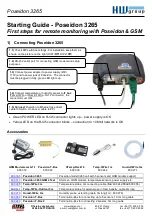
Starting Guide - Poseidon 3265
First steps for remote monitoring with Poseidon & GSM
1) Connecting Poseidon 3265
•
Green POWER LED on RJ45 connector lights up – power supply is OK
•
Yellow LED on the RJ45 connector blinks – connection to 10 Mbit network is OK
Accessories
600 165
Poseidon 3265
Poseidon model 3265 unit with 5 sensors and GSM modem support
600 313
Poseidon 3265 GSM2 Tset
Start set - GSM modem, temperature sensors, power supply etc.
600 005
Temp-1Wire 3m
Temperature probe, 3m connecting cable (1m=600 242,10m=600 056)
600 311
Temp-1Wire-Outdoor 3m
Temperature probe for external use in food industry, cable 3m long
600 279
Humid-1Wire 3m
Humidity probe, extending cable 3m long(1m= 600 278)
600 040
Poseidon T-Box
Termination-Box for connecting up to 5 sensors, 10 cm long cable
600 280
Poseidon T-Box2
Termination-Box for connecting 2 sensors, 3m long cable
Poseidon 3265
1.4) Connect temperature or humidity sensor to IT bus
(Temp-1Wire or Humid-1Wire - RJ12 connector), the
connector must click.
1.3) Connect power adapter to power supply (230 /
110V) and to power jack of Poseidon. The connector
must be plugged in fully, green LED lights up.
1.1) Check DIP switches settings. For installation keep them as
shown on the picture on the right (DIP1=Off, DIP2=Off).
1.2) RS-232 serial port for connecting GSM modem and setup
purposes.
1.5) Connect Poseidon to Ethernet (use direct
cable to Switch, cross-over cable to PC)
GSM Modemcom G10
600 312
Poseidon T-Box
600 040
HTemp-Rack19
600 330
Temp-1Wire 1m
600 242
Humid-1Wire 3m
600 279