10
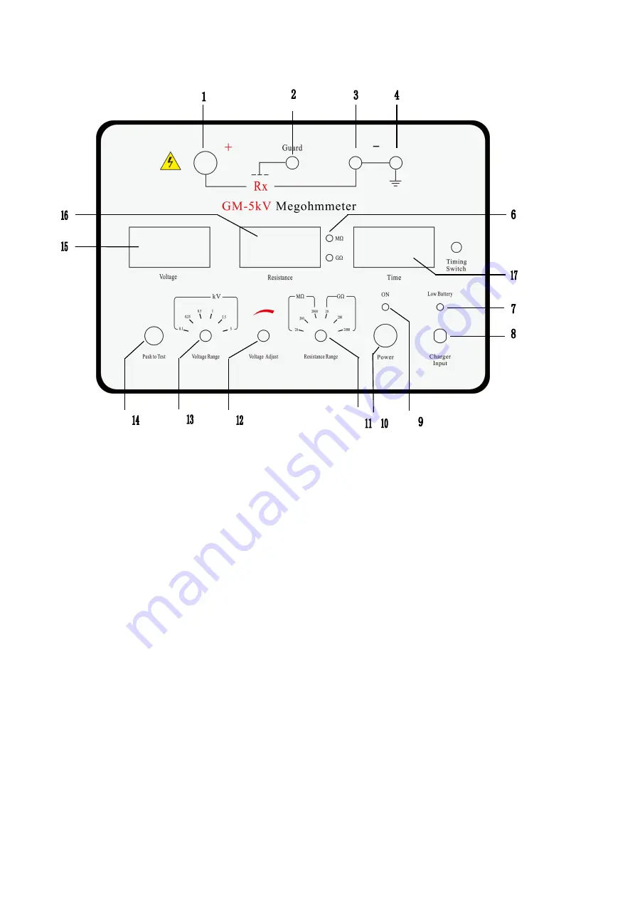
V. Panel layout
1. +: HV output
2.Guard: protection
3/4. -: earth
5. "Resistance gear" indication
6. Timing switch
7.low battery
8. “charger input”
9. “ON”
10. Power
11. Resistance range
12. “Voltage adjust”
13. Voltage range
14. “Push to test”
15 . “kV” meter
16. “MΩ/GΩ” meter
17.”time”meter
Note :
1. "+" HV output terminal: it is also called a line terminal; it uses
2. high-voltage cable to connect measured target such as the transformer,
motor windings and cable cores.
2. "Guard" protection terminal: when using “three-electrode method”
measure the volume resistance of insulation material and cables, "G" should
be connected to three-electrode guard ring. Guard ring is used to eliminate the


