Hvac CVH8 Скачать руководство пользователя страница 38

CVH8, HVH8, TVH8, VA9, HVA9, TVA9: APPLICATION GUIDELINE & SERVICE MANUAL

Manufacturer reserves the right to change, at any time, specifications and designs without notice and without obligations.

38

4. Use slip couplings to install new valve with stubs back into system.

Even  if  stubs  are  long,  wrap  valve  with  a  wet  rag  to  prevent

overheating.

5. After  valve  is  brazed  in,  check  for  leaks.  Evacuate  and  charge

system.  Operate  system  in  both  modes  several  times  to  be  sure

valve functions properly.

A88342

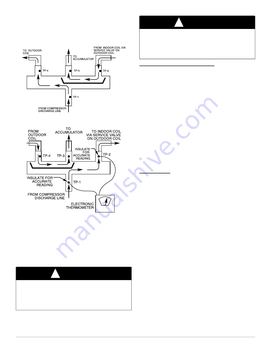
Fig. 40 – eversing Valve

(Cooling Mode or Defrost Mode, Solenoid Energized)

A88341

Fig. 41 – Reversing Valve

(Heating Mode, Solenoid De-Energized)

Liquid Line Filter Drier

Filter  driers  are  specifically  designed  for  R-22  or R-410A  refrigerant.

Only  operate  with  the  appropriate  drier  using  factory  authorized

components.  

It is recommended that the liquid line drier be installed at the indoor unit.

Placing the drier near the TXV allows additional protection to the TXV

as the liquid line drier also acts as a strainer. 

Install Liquid-line Filter Drier Indoor

Install filter drier as follows:

1. Braze 5 in. liquid tube to the indoor coil.
2. Wrap filter drier with damp cloth.  
3. Braze filter drier to 5 in. long liquid tube from step 1. 
4. Connect and braze liquid refrigerant tube to the filter drier. 

Suction Line Filter Drier

The suction line drier is specifically designed to operate with R-410A,

use only factory authorized components. Suction line filter drier is used

in cases where acid might occur, such as burnout. Heat pump units must

have the drier installed between the compressor and accumulator only.

Remove after 10 hours of operation. Never leave suction line filter drier

in a system longer than 72 hours (actual time).

Thermostatic Expansion Valve (TXV)

All fan coils and furnace coils will have a factory installed thermostatic

expansion valve (TXV).  The TXV will be a bi-flow, hard-shutoff with

an external equalizer and a balance port pin.  A hard shut-off TXV does

not have a bleed port.  Therefore,  minimal equalization takes place after

shutdown.  TXVs are specifically designed to operate with R-410A or

R-22  refrigerant,  use  only  factory  authorized  TXV’s.   

Do  not

interchange R-410A and R-22 TXVs.

TXV Operation

The TXV is a metering device that is used in air conditioning and heat

pump systems to  adjust  to changing load conditions  by  maintaining a

preset  superheat  temperature  at  the  outlet  of  the  evaporator  coil.  The

volume of refrigerant metered through the valve seat is dependent upon

the following: 

1. Superheat  temperature  is  sensed  by  cap  tube  sensing  bulb  on

suction  tube  at  outlet  of  evaporator  coil.  This  temperature  is

converted  into  pressure  by  refrigerant  in  the  bulb  pushing

downward  on the  diaphragm which opens the  valve via the push

rods.

2. The  suction  pressure  at  the  outlet  of  the  evaporator  coil  is

transferred via the external equalizer tube to the underside of the

diaphragm.  This is needed to account for the indoor coil pressure

drop.  Residential coils typically have a high pressure drop, which

requires this valve feature.

3. The pin is spring loaded, which exerts pressure on the underside of

the  diaphragm.  Therefore,  the  bulb  pressure  works  against  the

spring pressure and evaporator suction pressure to open the valve. 

If the load increases, the temperature increases at the bulb, which

increases the pressure on the top side of the diaphragm. This opens

the  valve  and  increases  the  flow  of  refrigerant.  The  increased

refrigerant  flow  causes  the  leaving  evaporator  temperature  to

decrease.  This lowers the pressure on the diaphragm and closes the

pin. The refrigerant flow is effectively stabilized to the load demand

with negligible change in superheat.

CAUTION

!

UNIT DAMAGE HAZARD

Failure  to  follow  this  caution  may  result  in  equipment  damage  or

improper operation.
To avoid performance loss and compressor failure, installation of filter

drier in liquid line is required.

CAUTION

!

UNIT DAMAGE HAZARD

Failure  to  follow  this  caution  may  result  in  equipment  damage  or

improper operation.
To avoid filter drier damage while brazing, filter drier must be wrapped

in a heat-sinking material such as a wet cloth.

Содержание CVH8

Страница 1: ...safety glasses protective clothing and work gloves Use quenching cloth for brazing operations Have fire extinguisher available Read these instructions thoroughly and follow all warnings or cautions in...

Страница 2: ...7 8 9 10 11 12 Example Part Number V A 9 24 G K A 1 0 0 Brand V Variable Speed KEY CHARACTERISTIC A Air Conditioner H Heat Pump TYPE 6 16 SEER 7 17 SEER 8 18 SEER 9 19 SEER NOMINAL EFFICIENCY 24 24 00...

Страница 3: ...t of comfort with the convenience of fingertip trouble shooting and diagnostic capability These units can also use a standard 2 stage or single stage thermostat for limited functionality ELECTRICAL Ta...

Страница 4: ...field electrical connections for tightness This should also be done after unit has reached operating temperatures especially if aluminum conductors are used Unit Electrical Power Power wires from the...

Страница 5: ...h cooling and dehumidification As the building load increases the motor will increase speed until it is at maximum speed at the maximum building load At unit start up there is a slight delay and thrus...

Страница 6: ...ommunication The green LED will be turned off when using a standard 2 stage non communicating heat pump thermostat Amber Status Light Amber colored STATUS light indicates operation and error status Se...

Страница 7: ...80ft 24 4 m or less allow system to operate in cooling mode at least 25 minutes If conditions are favorable check system charge by subcooling method If any adjustment is necessary adjust charge slowly...

Страница 8: ...n Cooling Mode CVH8 HVH8 TVH848 A200333 Fig 14 Charging in Cooling Mode CVH8 HVH8 TVH860 Table 5 Required Charge Adjustment for Indoor Coil Model AC Furnace Coil or Fan Coil Model 24 25 36 37 48 49 60...

Страница 9: ...echarge refer to the unit rating plate and indoor fan coil furnace coil per Table 4 and Table 5 for additional charge needed Refrigerant charge adjustment amount for adding or removing 0 6 oz ft 17 74...

Страница 10: ...tify the type and size of unit to the control On new units the model and serial numbers are inputted into the AOC board s memory at the factory If a model plug is lost or missing at initial installati...

Страница 11: ...alant before the cap is reinstalled The factory RTV can be reused as long as none of it has been removed during the cap removal 8 Reinstall compressor sound blanket making sure discharge thermistor an...

Страница 12: ...stage occurs suction pressure is checked at each stage in between current and demanded stage This is to prevent ramping of compressor speed too quickly and creating a low pressure situation As long as...

Страница 13: ...istor comparisons are not performed during low ambient cooling or defrost operation Failed Thermistor Default Operation Factory defaults have been provided in the event of failure of outdoor air therm...

Страница 14: ...d Damaged Model Plug Check model plug for corrosion or breakage replace if necessary Check Model Plug resistance per the wiring diagram Model Plug not fully engaged on board Align per the silkscreen l...

Страница 15: ...ity see resistance chart to check resistance at given temperature Broken or Damaged Sensor Check harness for continuity see resistance chart to check resistance at given temperature Hardware damage to...

Страница 16: ...eading to gage reading at service valve see transducer measurement chart Check system for electrical shorts and correct replace transducer Heat damage during brazing Compare transducer reading to gage...

Страница 17: ...STAGE 2 WARMUP DELAY 10 Minutes Both High voltage power cycle No action 69 System Malfunction INVERTER COMPRESS OR INTERNAL FAULT Elevates to this fault code after 5 hidden occurrences of itself 15 M...

Страница 18: ...ow too low or off Troubleshoot outdoor fan motor and make sure it is working Reversing Valve Bypass or Reversing Valve not energized Reversing Valve stuck halfway Ensure AOC fuse is good 24 VDC in coo...

Страница 19: ...Incoming power supply voltage Check voltage versus unit rating plate for allowable range Loose or incorrect wire connections Check incoming power leads and leads to the compressor plug 79 Local COMPR...

Страница 20: ...ction Cool Restriction in Circuits or Tubing Repair restriction Heat EXV Malfunction Troubleshoot EXV see guide below Heat Service Valve left closed Liquid Service Valve Ensure Liquid Service Valve is...

Страница 21: ...ndoor coil or filter for restriction debris and clean if necessary Heat Furnace plus Heat pump application Furnace stuck on If not in Defrost and Furnace is running same time as heat pump troubleshoot...

Страница 22: ...ent heating or high ambient cooling Over charge Check system charge Inverter damage Replace inverter 91 Local INVERTER VDC OUT OVER VOLTAGE EVENT Elevates to fault code 97 after 5 occurrences 5 Minute...

Страница 23: ...rter will reduce speed to a lower stage Both Refer to fault code 99 99 System Malfunction HIGH TORQUE LOCKOUT Elevated from fault code 98 when 98 occurs at lowest stage 2 hours Cool Overcharged System...

Страница 24: ...olt connection status OK between AOC and MOC Off No Power Table 12 AOC LED Descriptions Sizes 25 36 37 48 49 AND 60 Reference Color Status Description STATUS Amber Steady On AOC status standby mode Bl...

Страница 25: ...Table 16 AOC LED Descriptions Size 24 Reference Color Status Condition Description STATUS Amber Steady On Normal AOC status standby mode Blinking Abnormal AOC function fault status COMM Green Steady...

Страница 26: ...res securing the compressor power harness to the control box Remove compressor power harness from control box Replace wire tie with supplied wire tie do not fasten at this time The second wire tie for...

Страница 27: ...pushing one side down then the other NOTE DO NOT SCRAP SEALANT A210665 13 Reinstall compressor sound blanket making sure discharge thermistor and compressor power harness are routed as they were from...

Страница 28: ...and Black 8 Disconnect fan motor power harness plug 9 Disconnect reversing valve PEV plug See Figure Below 10 Disconnect high pressure switch plug 11 Disconnect EXV plug 12 Disconnect suction pressure...

Страница 29: ...MANUAL Manufacturer reserves the right to change at any time specifications and designs without notice and without obligations 29 A210667 Fig 32 Compressor and Fan Harness Unit sizes 25 36 37 48 49 an...

Страница 30: ...E MANUAL Manufacturer reserves the right to change at any time specifications and designs without notice and without obligations 30 A210669 Fig 34 Wire Harness Connections Unit sizes 25 36 37 48 49 an...

Страница 31: ...control box Replace wire tie with one supplied do not fasten at this time The second wire tie for the choke on the compressor is supplied with new harness on the replacement compressor highlighted wi...

Страница 32: ...that terminal cover remain installed during compressor installation 15 Using caution and the appropriate lifting device place replacement compressor in unit and secure with appropriate mounting hardw...

Страница 33: ...icates clean system 28 Check system for normal operation If unit is a heat pump switch from heating to cooling a few times to verify component operation Severe Burnout Perform steps 1 22 as specified...

Страница 34: ...VICE MANUAL Manufacturer reserves the right to change at any time specifications and designs without notice and without obligations 34 WIRING DIAGRAMS VA9 A160127 Fig 36 VA9 WIRING DIAGRAM Size 24 A16...

Страница 35: ...ICE MANUAL Manufacturer reserves the right to change at any time specifications and designs without notice and without obligations 35 WIRING DIAGRAMS VH8 A160129 Fig 38 VH8 WIRING DIAGRAM Size 24 A160...

Страница 36: ...still hot 2 Silver brazing alloy is used on copper to brass copper to steel or copper to copper Flux is required when using silver brazing alloy Do not use low temperature solder 3 Fluxes should be u...

Страница 37: ...at completion of the procedure Attach recovery system or vacuum pump to gauge set as needed for the service procedure The service valves must be open to evacuate the unit through the line set service...

Страница 38: ...ave a bleed port Therefore minimal equalization takes place after shutdown TXVs are specifically designed to operate with R 410A or R 22 refrigerant use only factory authorized TXV s Do not interchang...

Страница 39: ...em Pour and measure oil quantity if any from old accumulator If more than 20 percent of oil charge is trapped in accumulator add new POE oil to compressor to make up for this loss REFRIGERATION SYSTEM...

Страница 40: ...replace liquid line filter drier evacuate system and recharge with correct refrigerant quantity Coil Removal Coils are easy to remove if required for compressor removal or to replace coil 1 Shut off...

Отзывы: