background image

Rev.0208

5

back and side to side on inside bulkheads at joint.

8. Attach sections together via a 2 bolts located in the

base of the case.  Secure the overhead structure by
bolting the bracket, located inside behind lights.

9. Apply bead of silicone to top of bulkheads and slip

on stainless steel bulkhead cap.  Also apply silicone
to seam between overhead light tubes.

10.Use finger to smooth silicone as thin as possible at

masking tape on inside and outside of rear mullion
(apply additional silicone if necessary). Remove tape
applied on line #3.

CORNER WEDGES

Corner wedges are attached via front and rear
camlocks. Use a 7mm allen wrench to turn the locks.
Do not overtighten! Join the top by using a joint
bracket (included in joint kit) with 3/8" bolts.

JOINT TRIM

After cases have been leveled and joined, and refrigera-
tion, electrical, and wasted piping work completed, install
the splashguards. Fasten along the top edge, or center, with
#10 X 3/8" sheet metal screws.

 D

O

 N

OT

 S

EAL

 J

OINT

 T

RIM

 T

O

 F

LOOR

!

Installing R3HTO, R3HATO

All cases were tested at a level state before shipping. When
joining, use a carpenters level and shim enclosing or sup-
porting cabinet accordingly.

1. Make sure the cabinet you are installing the

R3HATO on is level.

2. Wire unit according to local codes.

Plumbing

WASTE OUTLET AND P-TRAP

The waste outlet is located off the center of the case on
one side allowing drip piping to be run lengthwise under
the fixture. There are 3 drains in each fixture that can be
easily located.
1-1/2",1", & 3/4" P-traps and threaded adapters are sup-
plied with each fixture. The 3 P-traps must be installed to
prevent air leakage and insect entrance into the fixture.

NOTE: PVC-DWV solvent cement is recommended.

Follow the manufacturer’s instructions.

INSTALLING CONDENSATE DRAIN

Poorly or improperly installed condensate drains can se-
riously interfere with the operation of this refrigerator,
and result in costly maintenance and product losses. Please
follow the recommendations listed below when installing
condensate drains to insure a proper installation:

1. Never use pipe for condensate drains smaller than

the nominal diameter of the pipe or P-trap supplied
with the case.

2. When connecting condensate drains, the P-trap

must be used as part of the condensate drain to
prevent air leakage or insect entrance. Store plumb-
ing system floor drains should be at least 14" off the
center of the case to allow use of the P-trap pipe
section. Never use two water seals in series in any
one line. Double P-traps in series will cause a lock
and prevent draining.

3. Always provide as much down hill slope (“fall”) as

possible; 1/8" per foot is the preferred minimum.
PVC pipe, when used, must be supported to main-
tain the 1/8" pitch and to prevent warping.

4. Avoid long runs of condensate drains. Long runs

make it impossible to provide the “fall” necessary for
good drainage.

5. Provide a suitable air break between the flood rim of

the floor drain and outlet of condensate drain. 1" is
ideal.

6. Prevent condensate drains from freezing:

a. Do not install condensate drains in contact with

non-insulated suction lines. Suction lines should be
insulated with a nonabsorbent insulation material
such as Armstrong’s Armaflex.

b. Where condensate drains are located in dead air

spaces (between refrigerators or between a
refrigerator and a wall), provide means to prevent
freezing. The water seal should be insulated to
prevent condensation.

WATER SUPPLY

Tap water contains more minerals and will contribute to
the mineral residue and buildup which may impair the case's
performance and create undesireable cleaning issues. It is
recommended that a 5 micro particle filter be used to
filter the incoming water supply. Be sure to flush the wa-
ter line before hooking it up to the filter to prevent block-
ing the filter.

Refrigeration -

R3H, R3HA  with refrigerated front

REFRIGERANT TYPE

The standard refrigerant will be R-22 unless otherwise
specified on the customer order. Check the serial plate
on the case for information.

PIPING

The refrigerant line outlets are located under the case.
Locate first the electrical box, the outlets are then on the
same side of the case but at the opposite end. Insulate

Содержание Specialty Products R3H

Страница 1: ...A R3Combo Hot Top w Self Service Heat or Refrig Rev 0208 Installation Operation Manual R3H R3HTO R3HA R3Combo Hot Service Self Service Case with Self Service Front INSTALLATION OPERATION GUIDE p n IGFP R3 R3H R3P R3HA 0208 ...

Страница 2: ...ble shortages of mate rial If a shortage should exist and is found to be the re sponsibility of Hussmann Chino notify Hussmann Chino If such a shortage involves the carrier notify the carrier imme diately and request an inspection Hussmann Chino will acknowledge shortages within ten days from receipt of equipment HUSSMANN CHINO PRODUCT CONTROL The serial number and shipping date of all equipment h...

Страница 3: ...A with Hot Front Hot Air Top with Hot Front Option and Dry Rear Storage Scale 1 2 Optional 8 shelf Optional 12x20 pans Dry Rear Storage 8 1 8 20 5 8 Griddle Glow Ray T 5 Light 11 1 2 Heater T 5 Light 36 3 4 1 6 5 8 13 1 4 6 1 4 6 50 3 4 16 1 2 26 1 2 53 Water Reservoir Pan 11 1 8 1 5 5 8 26 1 4 8 3 4 33 1 8 26 1 8 R3HA Circulated Hot Air Merchandiser 34 1 4 Flange Cutout 32 1 4 9 1 Variable Cutout...

Страница 4: ... and prevent any stress on the front glass SETTING AND JOINING The sectional construction of these models enable them to be joined in line to give the effect of one continuous display A joint trim kit is supplied with each joint LEVELING IMPORTANT It is imperative that cases be leveled from front to back and side to side prior to joining A level case is necessary to insure proper operation water d...

Страница 5: ...elow when installing condensate drains to insure a proper installation 1 Never use pipe for condensate drains smaller than the nominal diameter of the pipe or P trap supplied with the case 2 When connecting condensate drains the P trap must be used as part of the condensate drain to prevent air leakage or insect entrance Store plumb ing system floor drains should be at least 14 off the center of t...

Страница 6: ...l be installed on the coil inlet coil outlet and in the discharge air Some supermarkets require a 4th sensor in the return air Case controllers will be located in the electrical raceway or under the case The front Self Service Evaporator has an E P R valve in stalled to maintain a constant discharge temperature It is located in the front at the right side of the case under the fan plenum near the ...

Страница 7: ...ction but always check the serial plate Ballasts are located within the access panel that runs the length of the rear of the case Refer to diagram below Windex or Glass Plus are the only solutions recom mended to be used to clean the non glare glass The dam age to the glass from improper caustic solutions is irrepa rable In addition to cleaning the glass with the recommended product there are prec...

Страница 8: ...ct Product temperature should always be main tained at a constant and proper temperature This means that from the time the product is received through stor age preparation and display the temperature of the prod uct must be controlled to maximize life of the product Hussmann cases were not designed to heat up or cool down product but rather to maintain an item s proper temperature for maximum shel...

Страница 9: ... case 30 minutes before loading product using higher settings Never place food directly into warmer Always use an inset and pan Never pour water into a dry preheated warmer This may damage the unit Always pour water into warmer BEFORE preheating Always use water in case wells as it provides even heat and humidity Too much water or too much heat will cause excessive condensation on the front glass ...

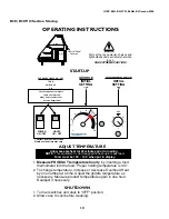
Страница 10: ... OVERHEAD HEAT INITIAL SETTING 5 GRIDDLE INITIAL SETTING 7 OPERATING INSTRUCTIONS Control Panel on Rear of Case Number of controls may vary LO HI 6 5 4 3 2 OFF 430 01 0365 9810 1 2 3 4 5 6 7 8 9 10 Sta r t u p LIGHTS ON OFF POWER ON OFF Allow case preheat for 45 minutes prior to loading NOTE This equipment is not designed to heat up or cook food Food must be 150 160 when put in display Parts of th...

Страница 11: ...an INSIDE the case 7 Turn Temperature Control knob to 7 STARTUP for initial temperature settings This will guarantee over 140 F safe FDA temperatures Temperature Adjustment Adjust temperature up or down as required to maintain safe FDA Hot FoodTemperatures After adjustment allow adequate time for change to take place Allow 30 minutes for product to respond Although a discharge air temperature of a...

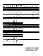
Страница 12: ... 4 208 240 1Ø 10 11 6 1 6 208 240 1Ø 15 17 8 2 4 208 240 1Ø 20 23 10 3 3 4 208 240 1Ø 25 28 12 3 4 208 240 1Ø 30 34 R3H Hot Cold Combo Use R3P Prep Top Front Section Only on the previous page in addition to the above Hot Top R3H Hot Front 4 1 4 1 208 240 1Ø 10 11 6 1 6 1 208 240 1Ø 19 22 8 2 4 1 208 240 1Ø 19 22 10 3 3 4 1 208 240 1Ø Consult Factory 12 3 4 1 208 240 1Ø Consult Factory R3HTO Stand ...

Страница 13: ...ail Case to Case Harness 125 04 0101 125 04 0105 ASCM SP 125 04 0201 BALLAST FULHAM WH3 120 L ASCM MP 125 04 0200 BALLAST FULHAM WH3 120 L BALLAST FULHAM WH3 120 L 2 F28TL5 830 125 01 1023 125 01 1024 1 F28TL5 830 SPARE Hard wired no 2 F28TL5 830 Shelf Top Front Canopy Top Front Canopy 125 01 1023 125 01 1024 1 F28TL5 830 Shelf 125 04 0108 Evaporator Fans Primary harness TOP CASE µ 125 01 0083 125...

Страница 14: ...ewWiring Single Case Pigtail Case to Case Harness 125 04 0101 125 04 0105 125 04 0108 Evaporator Fans Primary harness µ Cap 125 04 0119 Ü 125 04 0115 ASCM MP 125 04 0200 NOTE PLUG TOP CASE FANS OR REAR STORAGE COILS INTO HUMIDITY SYSTEM FANS µ MAIN POWER PANEL BYPASS HARNESS Ü POWER FEED FROM POWER PANEL THROUGH HARNESS 125 04 0115 REAR STORAGE T STAT REAR STORAGE SUCTION SOLENOID EVAPORATOR FAN E...

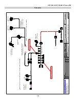
Страница 15: ...risci AEC Sheet of R3 8 Combo 4 Hot 4 Cold Top Serv R3 2000 Combo Case 1 2 3 4 5 6 7 P1 L Griddle Heater Pads 2 553 Watts 220 VAC Paktronics Controller Pilot Light Temp Control Pot Sensor L2 L1 P H2 H1 L Overhead Heater HE 00 43 1300 Watts 240 VAC L1 L2 N G DPST Relay Power Switch Pilot Light 208 240 VAC 50 60 Hz 3 3 08 03 00 W1800018 H Wiring Diagrams NewWiring LOADING 208 V 240 V L1 L2 L3 8 7 8 ...

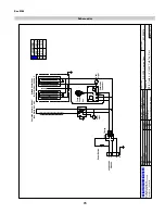
Страница 16: ...TIPPETTE 125 01 0311 BALLAST 125 01 3267 FULHAM LH4 120 L BALLAST 125 01 3267 FULHAM LH4 120 L L P H2 L2 L1 H1 PACKTRONICS CONTROLLER 225 01 3229 PILOT LIGHT L TEMP CONTROL SENSOR 225 01 3228 6 4 2 1 5 P1 3 7 CONTACTOR SQUARE D 8910DPA43V02 125 01 1001 L1 L2 L3 N G L MAIN POWER 208 240 VAC 3Ø 50 60 HZ 5W PILOT LIGHT CAP UNUSED RED LEAD CASE LIGHTING 3 FP28T5 830 LAMPS FRONT CASE TOP CASE SHELF HEA...

Страница 17: ...11 BALLAST 125 01 3267 FULHAM LH4 120 L CONTACTOR SQUARE D 8910DPA43V02 125 01 1001 L1 L2 L3 N G L MAIN POWER 208 240 VAC 3Ø 50 60 HZ 5W CASE LIGHTING 6 FP28T5 830 LAMPS FRONT CASE TOP CASE L P H2 L2 L1 H1 L P H2 L2 L1 H1 PACKTRONICS CONTROLLER 225 01 3229 PILOT LIGHT L TEMP CONTROL SENSOR 225 01 3228 6 4 2 1 5 P1 3 7 SHELF HEATER HATCO INFRA BLACK GLOWRAY 2 950 W 240 VAC 125 02 1086 CANOPY HEATER...

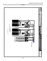
Страница 18: ...OF L P H2 L2 L1 H1 PACKTRONICS CONTROLLER 225 01 3229 PILOT LIGHT L TEMP CONTROL SENSOR 225 01 3228 6 4 2 1 5 P1 3 7 CANOPY HEATER DEKKO HE 00 43 2 1300 W 240 VAC 125 01 3227 L P H2 L2 L1 H1 PACKTRONICS CONTROLLER 225 01 3229 PILOT LIGHT L TEMP CONTROL SENSOR 225 01 3228 6 4 2 1 5 P1 3 7 GRIDDLE HEATER THERMOFLEX 4 342 W 240 VAC 225 01 6787T TOP HOT CASE WIRING L1 L2 L3 SEE SHEET 1 OF 2 FOR LOWER ...

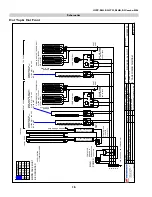
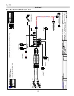
Страница 19: ... PRIMARY HARNESS SELF SERVICE FRONT SECTION EVAPORATOR FANS CAP FRONT CANOPY TOP HARD WIRED NO HARD WIRED NO FRONT CANOPY TOP 115V 15 AMP RECEPTACLE OPTIONAL 115 V 20 AMP GFCI RECEPTACLE DEDICATED LINE OPTIONAL LIGHT SWITCH SINGLE CASE PIGTAIL CASE TO CASE HARNESS LEDGE LIGHTS OPTIONAL SEE WIRING W0100016 H WIRESCHEMATICS NEWWIRE W1800034 R3 CASES 4 CASE DIAGRAM COLD FRONT 1 SHELF STD HOT TOP DRY ...

Страница 20: ...OF 2 2 H WIRESCHEMATICS NEWWIRE R3 CASES 4 CASE DIAGRAM COLD FRONT 1 SHELF CIRCUIT 2 HOT TOP SECTION ONLY 05 16 01 W1800034 STD HOT TOP DRY REAR STORAGE OVERHEAD HEATER HE 00 43 1 1300 W 240 VAC GRIDDLE HEATER PADS 2 553W 240VAC PACKTRONICS CONTROLLER 225 01 3229 PILOT LIGHT L TEMP CONTROL SENSOR 225 01 3228 6 4 2 1 5 P1 3 7 L P H2 L2 L1 H1 125 01 3182 OMRON RELAY G7L 2A TUBJ CB L1 L2 L3 N G L MAI...

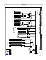
Страница 21: ...4 0140 125 04 0140 125 04 0140 EVAPORATOR FANS PLENUM EXTENSION PRIMARY HARNESS SELF SERVICE FRONT SECTION 125 04 0109 EVAPORATOR FANS CAP FRONT CANOPY TOP HARD WIRED NO HARD WIRED NO FRONT CANOPY TOP SHELF HARD WIRED NO FRONT CANOPY TOP SHELF 115V 15 AMP RECEPTACLE OPTIONAL 115 V 20 AMP GFCI RECEPTACLE DEDICATED LINE OPTIONAL LIGHT SWITCH SINGLE CASE PIGTAIL CASE TO CASE HARNESS LEDGE LIGHTS OPTI...

Страница 22: ...IRESCHEMATICS NEWWIRE R3 CASES CIRCUIT 2 HOT TOP SECTION ONLY 05 16 01 STD HOT TOP DRY REAR STORAGE OVERHEAD HEATERS 1 HE 05 67 2100 W 240 VAC GRIDDLE HEATER PADS 3 553W 240VAC PACKTRONICS CONTROLLER 225 01 3229 PILOT LIGHT L TEMP CONTROL SENSOR 225 01 3228 6 4 2 1 5 P1 3 7 L P H2 L2 L1 H1 INFINITE CONTROL 125 01 3182 OMRON RELAY G7L 2A TUBJ CB L1 L2 L3 N G L MAIN POWER 208 240 VAC 1Ø 50 60 HZ 4W ...

Страница 23: ...4 0140 125 04 0140 125 04 0140 EVAPORATOR FANS PLENUM EXTENSION PRIMARY HARNESS SELF SERVICE FRONT SECTION 125 04 0109 EVAPORATOR FANS CAP FRONT CANOPY TOP HARD WIRED NO HARD WIRED NO FRONT CANOPY TOP SHELF HARD WIRED NO FRONT CANOPY TOP SHELF 115V 15 AMP RECEPTACLE OPTIONAL 115 V 20 AMP GFCI RECEPTACLE DEDICATED LINE OPTIONAL LIGHT SWITCH SINGLE CASE PIGTAIL CASE TO CASE HARNESS LEDGE LIGHTS OPTI...

Страница 24: ...CIRCUIT 2 HOT TOP SECTION ONLY 05 16 01 W1800036 STD HOT TOP DRY REAR STORAGE OVERHEAD HEATERS HE 00 43 2 1300 W 240 VAC GRIDDLE HEATER PADS 2 553W 240VAC PACKTRONICS CONTROLLER 225 01 3229 PILOT LIGHT L TEMP CONTROL SENSOR 225 01 3228 6 4 2 1 5 P1 3 7 GRIDDLE HEATER PADS 2 553W 240VAC PACKTRONICS CONTROLLER 225 01 3229 PILOT LIGHT L TEMP CONTROL SENSOR 225 01 3228 6 4 2 1 5 P1 3 7 L P H2 L2 L1 H1...

Страница 25: ...4 0140 125 04 0140 EVAPORATOR FANS PLENUM EXTENSION PRIMARY HARNESS SELF SERVICE FRONT SECTION 125 04 0109 125 04 0109 EVAPORATOR FANS EVAPORATOR FANS PLENUM EXTENSION CAP FRONT CANOPY TOP HARD WIRED NO HARD WIRED NO FRONT CANOPY TOP SHELF HARD WIRED NO FRONT CANOPY TOP SHELF 115V 15 AMP RECEPTACLE OPTIONAL 115 V 20 AMP GFCI RECEPTACLE DEDICATED LINE OPTIONAL SHELF LIGHT SWITCH SINGLE CASE PIGTAIL...

Страница 26: ... 15 01 STD HOT TOP DRY REAR STORAGE 208 240 VAC 1Ø 50 60 HZ 4W CONTACTOR MAIN POWER L L1 L2 L3 N G OVERHEAD HEATERS 1 HE 00 43 1300 W 240 VAC 1 HE 05 67 2100 W 240 VAC GRIDDLE HEATER PADS 2 553W 240VAC PACKTRONICS CONTROLLER 225 01 3229 PILOT LIGHT L TEMP CONTROL SENSOR 225 01 3228 6 4 2 1 5 P1 3 7 GRIDDLE HEATER PADS 3 553W 240VAC PACKTRONICS CONTROLLER 225 01 3229 PILOT LIGHT L TEMP CONTROL SENS...

Страница 27: ... 125 04 0140 EVAPORATOR FANS PLENUM EXTENSION PRIMARY HARNESS SELF SERVICE FRONT SECTION 125 04 0109 125 04 0109 EVAPORATOR FANS EVAPORATOR FANS PLENUM EXTENSION CAP FRONT CANOPY TOP HARD WIRED NO HARD WIRED NO FRONT CANOPY TOP SHELF HARD WIRED NO FRONT CANOPY TOP SHELF 115V 15 AMP RECEPTACLE OPTIONAL 115 V 20 AMP GFCI RECEPTACLE DEDICATED LINE OPTIONAL SHELF LIGHT SWITCH SINGLE CASE PIGTAIL CASE ...

Страница 28: ...HOT TOP SECTION ONLY 05 15 01 W1800038 STD HOT TOP DRY REAR STORAGE L P H2 L2 L1 H1 L P H2 L2 L1 H1 L P H2 L2 L1 H1 208 240 VAC 1Ø 50 60 HZ 4W CONTACTOR MAIN POWER L L1 L2 L3 N G OVERHEAD HEATERS HE 00 43 3 1300 W 240 VAC GRIDDLE HEATER PADS 2 553W 240VAC PACKTRONICS CONTROLLER 225 01 3229 PILOT LIGHT L TEMP CONTROL SENSOR 225 01 3228 6 4 2 1 5 P1 3 7 GRIDDLE HEATER PADS 2 553W 240VAC PACKTRONICS ...

Страница 29: ...SAC VTP1A 0 5 M Ω OFF TIME ADJ SSAC YP100416 1 M Ω WATER SOLENOID 204CD B B EMS 225 01 3083 125 01 3267 CAP IF NOT USED CANOPY LIGHT FP28T5 830 SHELF LIGHT FP28T5 830 OPTIONAL TEMP SENSOR 225 01 3228 SAFETY T STAT NGT 11S11T444 225 01 3301A PILOT LIGHT TEMPERATURE ADJ RELAY OMRON G7L 2A TUBJ CB 125 01 3182 TRAK STAT 225 01 3229 POWER SUPPLY 208 VAC 1 Ø 50 60 Hz 4 WIRE 3 2 1 4 5 6 7 TIMER SSAC ESDR...

Страница 30: ... 125 01 3267 CANOPY LIGHTS 2 FP28T5 830 SHELF LIGHT FP28T5 830 OPTIONAL TEMP SENSOR 225 01 3228 SAFETY T STAT NGT 11S11T444 225 01 3301A PILOT LIGHT TEMPERATURE ADJ RELAY OMRON G7L 2A TUBJ CB 125 01 3182 TRAK STAT 225 01 3229 HEATER HE 25 125 02 1096 1300 W 240 VAC AXIAL FANS COMAIR MX2B1 EL 225 01 2012 M BL BK W R G M POWER SUPPLY 208 VAC 1 Ø 50 60 Hz 4 WIRE 3 2 1 4 5 6 7 TIMER SSAC ESDR450A2 HEA...

Страница 31: ...OT LIGHT TEMPERATURE ADJ RELAY OMRON G7L 2A TUBJ CB 125 01 3182 TRAK STAT 225 01 3229 HEATER HE 25 125 02 1096 1300 W 240 VAC AXIAL FANS COMAIR MX2B1 EL 225 01 2012 M BL BK W R G M POWER SUPPLY 208 VAC 1 Ø 50 60 Hz 4 WIRE 3 2 1 4 5 6 7 TIMER SSAC ESDR450A2 HEATER FANS G GROUND BK W BL R G R W BK BL SAFETY T STAT NGT 11S11T444 225 01 3301A HEATER HE 25 125 02 1096 1300 W 240 VAC AXIAL FANS COMAIR M...

Страница 32: ...40VAC 50 60 Hz 3Ø 5W GRIDDLE HEATER PADS 2 342W 240VAC PILOT LIGHT TRAK STAT 225 01 3229 TEMPERATURE ADJ TEMP SENSOR 225 01 3228 L H1 L1 L2 H2 P 7 3 P1 5 1 2 4 6 L H1 L1 L2 H2 P HATCO GLOWRAY HEATERS 2 950W 240VAC 125 02 1086 BALLAST 125 01 3267 FULHAM LH4 120 L L FRONT CASE LIGHT SWITCH FRONT SHELF CANOPY LIGHT 2 FP28T5 830 LAMPS TO UPPER CASE SECTION TERMINAL BLOCK SEE PAGE 2 OF 2 NOTE CASE MUST...

Страница 33: ... YP100416 1 M Ω WATER SOLENOID 204CD B B EMS 225 01 3083 125 01 3267 CAP IF NOT USED CANOPY LIGHT FP28T5 830 SHELF LIGHT FP28T5 830 OPTIONAL TEMP SENSOR 225 01 3228 SAFETY T STAT NGT 11S11T444 225 01 3301A PILOT LIGHT TEMPERATURE ADJ RELAY OMRON G7L 2A TUBJ CB 125 01 3182 TRAK STAT 225 01 3229 POWER SUPPLY 208 VAC 1 Ø 50 60 Hz 4 WIRE 3 2 1 4 5 6 7 TIMER SSAC ESDR450A2 M BL BK W R G M AXIAL FANS CO...

Страница 34: ...h normal refrigeration practices Refrigeration piping should be insulated according to Hussmann s recommendations 1 3 A clogged waste outlet blocks refrigeration The installer is responsible for the proper installation of the system which dispenses condensate waste through an air gap into the building indirect waste system 1 4 The installer should perform a complete start up evaluation prior to th...

Страница 35: ...roperly If it is determined that such condition is undesirable i e the product is above proper temperature checks should be made for the following 1 Has the refrigerator been loaded with warm product 2 Is the product loaded beyond the Safe Load Line markers 3 Are the return air ducts blocked 4 Are the entering air ducts blocked 5 Is a dumped display causing turbulent air flow and mixing with room ...

Страница 36: ... be kept closed during periods of inactivity f Minimize the transfer time of perishables from storage to display g Keep meat under refrigeration in meat cutting and processing area except for the few moments it is being handled in processing When a cut or tray of meat is not to be worked on immediately the procedure should call for returning it to refrigeration h Keep tools clean and sanitized Sin...

Страница 37: ...rring hot foods to room temperature pans can cause the temperature of the food to drop 20 or more thus causing food to be at an unsafe serving temperature 12 Clean spills as they happen simply by wiping with a cloth Be sure to use a dry cloth on very hot surfaces to prevent steam burns 13 Turn the equipment off and allow to cool before cleaning 14 To remove baked on splatter from Stainless Steel t...

Страница 38: ...IGFP R3H R3HTO R3HA R3Combo 0208 38 ...

Страница 39: ...mann equipment Hussmann s sole obligation under this warranty shall be limited to a period not to exceed five years from date of factory shipment On Hussmann refrigeration systems an additional 4 year extended warranty for the motor compressor assembly is available but must be purchased prior to shipment to be in effect Hussmann reserves the right to inspect the job site installation and reason fo...

Страница 40: ...r your particular unit They can be found on a small metal plate on the unit Please note them below for future reference MODEL SERIAL NUMBER Chino Additional copies of thispublication may be obtained by contacting Hussmann Chino 13770 RamonaAvenue Chino California 91710 909 628 8942 FAX 909 590 4910 800 395 9229 Service Record Last service date By ...

Отзывы: