background image

Troubleshooting Schedule

Problem

Cause

Engine will not start

See the "Checking the Safety System" section if the controls are in the wrong position
There is no fuel in the fuel tank
Spark plug defective
Dirt in the carburetor or fuel line
Starter does not turn over the engine
Bad or old fuel in the fuel tank
Incorrect fuel in the fuel tank

Starter does not turn over the engine

Battery flat
Main fuse blown. The fuse is found in front of the battery, under the engine cover
Bad contact between the cable and battery terminal
Ignition lock faulty
Faulty starter

Engine does not run smoothly

Throttle in the choke position
Clogged air filter
Fuel tank vent blocked
Faulty spark plug
Dirt in the carburetor or fuel line
Carburetor incorrectly set
Incorrect ignition setting

Engine lacks power

Throttle in the choke position
Clogged air filter
Faulty spark plug
Dirt in the carburetor or fuel line
Carburetor incorrectly set

Engine overheats

Engine overloaded
Air intake or cooling fins clogged
Fan damaged
Too little or no oil in the engine
Faulty spark plug

Battery does not charge

One or more battery cells faulty
Poor contact on the battery terminal cable connectors

The ride-on mower vibrates

Blades are loose
One or more blades unbalanced, caused by damage or poor balancing after sharpening

Uneven mowing

Blades blunt
Tall or wet grass
Grass build-up under the cover
Different tire pressures on right and left sides
Driving speed too high
Engine speed too low
Cutting deck rear drive belt slips

TROUBLESHOOTING CHART

English

 – 20

Содержание G125-85F

Страница 1: ...Workshop Manual English M 105 125 85F G 125 85F ...

Страница 2: ...g Shaft 12 Dismantling Assembling the Cable Pulley 12 Checking and Adjusting the Brake 13 Adjusting the Throttle Cable 13 Dismantling the Swing Axle 14 Dismantling Assembling the Drive Chain 14 Adjusting the Drive Chain 14 Dismantling the Gearbox 14 Dismantling Assembling the Hydrostatic Transmission 15 Replacing the Belts 16 Checking and Adjusting the Cutting Deck Ground Pressure 16 Removing the ...

Страница 3: ...ye protection when working with tensioned springs Use hearing protection during testing During testing do not touch the muffler before it has cooled down Risk of burns This is especially true if the ride on mower is equipped with a catalytic converter The coatings on and in the catalytic converter element are hazardous to ingest Use protective gloves when working with the converter muffler The bla...

Страница 4: ...t pin 15 A Noise Emissions and CuttingWidth see note 2 Sound power level measured dB A 98 99 98 Sound power level guaranteed dB A 99 99 99 Cutting width cm inch 85 33 5 85 33 5 85 33 5 Noise Levels see note 3 Noise pressure level at the operator s ear dB A 84 85 84 Vibration Levels see note 4 Vibration level in steering wheel m s2 4 3 4 3 4 3 Vibration level in seat m s2 1 3 1 3 1 3 Transmission M...

Страница 5: ...e tires t Lubricate joints and shafts 3 t Check the V belts l Check and adjust the throttle cable l Change the fuel filter m Change the spark plug t Check the fuel hose Change if necessary 4 m 1 First change after 8 hours When operating with a heavy load or at high ambient temperatures change every 25 hours 2 Maintenance and changes are required more often in dusty conditions 3 The ride on mower s...

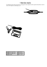
Страница 6: ...ecial tools are used when working on the rider Special tools for engine and transmission can be found in the respective workshop manual 1 Battery charger EU 580 35 52 01 1 Battery charger UK 580 35 52 02 2 Tachometer 502 71 14 01 1 2 ...

Страница 7: ...erial number on hydrostatic machines is stated on the bar code decal located on the front of the housing for the left hand drive shaft Thetypedesignationisstatedabovethebarcodeandstarts with the letter K The serial number is stated above the bar code and has the prefix s n Themanufacturer stypenumberisstatedunderthebarcode and has the prefix p n Please provide the type designation and serial numbe...

Страница 8: ...will lift the cutting deck to the transport position In order to activate the transport position the lock button on the steering column is then pressed and held in while the lift pedal is released If the lift pedal is released without pressing the lock button the cutting deck will be lowered cutting position To activate the cutting position press the pedal and then release it Thecuttingheightisadj...

Страница 9: ...ay to the starter Separate the connector Remove the side plates Loosen the screws Twist out the back of the plate 45 Remove the front edge of the plate Loosen the cable bracket from the engine Remove the fuel tank see Fuel Tank Remove the clip holding the throttle and choke cables Release the cable from its mounting Removetheplateovertheenginebylooseningthefourscrewsin theframe twooneachside Theen...

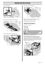
Страница 10: ...elTank Dismantling WARNING Petrol is highly flammable and environmentally hazardous Exercise caution to avoid fire and spillage Use a suitable vessel to collect the petrol Empty the petrol tank by removing the hose from the connector under the tank If you do not wish to empty the tank you can pinch the hose with lockable welding pliers and then remove the hose and hose clip from the fuel filter s ...

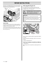
Страница 11: ... be changed after every 50 running hours WARNING Engine oil can be very hot if it is drained directly after stopping the engine Allow the engine to cool down first IMPORTANT Used engine oil is a health hazard and must not be disposed of on the ground or in the environment it should always be disposed of at an appropriate disposal site Avoid contact with skin Wash with soap and water in case of spi...

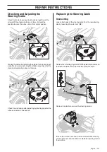
Страница 12: ... wire tension after adjusting by pinching together the wires see earlier in this section Replacing the Steering Cable Dismantling Loosen both ends of the steering cable from the rear steering disc by loosening the outer nuts M8 Remove the retaining rings and lift off the plastic sprockets and the washer between them from the two pulley brackets Remove the plastic cover over the steering column If ...

Страница 13: ...of both pulley brackets and connected to the rear steering disc on the right side of the machine Note that the wire must be placed in the groove in the plastic sprocket before it is all run back to the top of the shaft If the machine has hydrostatic transmission M125 97FH the right cable must be routed under the parking brake arm on the hydrostatic box and the left cable must be routed over the pa...

Страница 14: ...at the brakes are correctly adjusted by placing the ride on mower on a slight downhill slope with the clutch disengaged and activating the brake Adjusting theThrottle Cable The throttle cable may need to be adjusted if the engine does not respond as it should when accelerating i e if it produces black smoke or maximum revs are not reached Remove the bonnet Loosentheclampingscrewforthecable souterc...

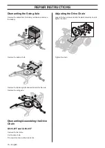
Страница 15: ...nd control rods for the axle Remove the swing axle Dismantling Assembling the Drive Chain M105 97F and G105 85F Remove the foot plate Cut the drive chain Fit a new drive chain with a master link Adjusting the Drive Chain Loosen the four screws and slide the plate forward by hand to tighten the chain Tighten the chain REPAIR INSTRUCTIONS 15 English ...

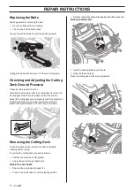
Страница 16: ...ox is fastened Loosen the gearbox retaining screws The nit must be tightened 50 2 Nm when changing the shift lever Dismantling Assembling the HydrostaticTransmission M125 85FH Loosen the cutting deck belt Loosen the idler spring Pry off the drive belt Remove the lock washer and unhook the throttle stay Remove the five screws holding the hydrostatic transmission REPAIR INSTRUCTIONS English 16 ...

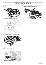
Страница 17: ... pressure with the adjuster nut located inside the ride on mower front wheel Ground pressure should be between 12 and 15 kg 26 5 33 lb Removing the Cutting Deck The cutting deck can be removed in order to facilitate cleaning and servicing To remove the cutting deck proceed as follows Position the machine on flat ground Apply and secure the parking brake M105 95F and G105 85F Depress the parking br...

Страница 18: ...e snap lock and lift off the front cover Loosen the spring for the drive belt tensioning wheel Lift off the drive belt Release the adjustment screw Loosen the split pin from the equipment frame Grasp the upper pipe construction of the deck and pull it out REPAIR INSTRUCTIONS English 18 ...

Страница 19: ... from the microswitch Press in the fasteners and remove the microswitch from the holder Blades Microswitch Loosen the left side cover Disconnect the connector from the microswitch Parking Brake Microswitch Remove the right side cover Disconnect the connector from the microswitch There are two microswitches one on each side Pedal Microswitch Disconnect the connector from the microswitch Main Fuse T...

Страница 20: ...ulty spark plug Dirt in the carburetor or fuel line Carburetor incorrectly set Incorrect ignition setting Engine lacks power Throttle in the choke position Clogged air filter Faulty spark plug Dirt in the carburetor or fuel line Carburetor incorrectly set Engine overheats Engine overloaded Air intake or cooling fins clogged Fan damaged Too little or no oil in the engine Faulty spark plug Battery d...

Страница 21: ...Electrical schedule Will be added ...

Страница 22: ...115 87 12 26 2017 02 08 ...

Отзывы: