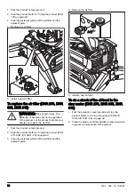
Husqvarna DXR 145 Скачать руководство пользователя страница 81

B

x4

A

A

C

30x

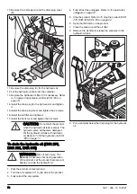
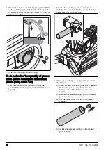
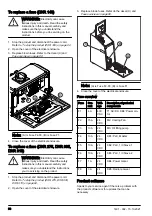
1. Move the product until you have access to all grease

nipples. The grease nipples are shown in the

illustration.

2. Stop the product and disconnect the power cord.

Refer to 

To stop the product (DXR 145) on page 62

.

3. Clean the grease nipples.
4. Replace broken or blocked grease nipples.
5. Lubricate the grease nipples with a grease gun.

Push the grease gun 2–3 times or until grease can

be seen at the edges. Refer to 

Lubricants on page

110

.

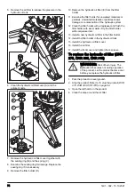
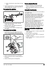
6. Lubricate all joints and cylinder mountings in the

outriggers.

7. Lubricate all joints and cylinder mountings in the arm

system.

8. Lubricate the 2 grease nipples (A) on the gear ring

bearing and the gears of the gear ring (B).
a) Extend the arm system until the arm system

points straight forward.

b) Open the inspection door (C) on the tower to get

access to the 2 grease nipples.

c) Lubricate the grease nipples with a grease gun.

Push the grease gun 2–3 times.

d) Start the product. Make sure that you are at a

safe distance. Refer to 

To start the product (DXR

145) on page 52

.

e) Turn the tower 180˚.
f) Stop the product and disconnect the power cord.

Refer to 

To stop the product (DXR 145) on page

62

.

g) Lubricate the grease nipples again with a grease

gun. Push the grease gun 2–3 times.

To lubricate the product (DXR 275,

DXR 305, DXR 315)

CAUTION: 

If the procedure for

lubrication is not followed, there is a high

risk that the seals of the gear ring are

pushed out. If the seals are pushed out, dirt

can go into the ball bearing of the gear ring

and cause damage. Damaged seals must

be replaced.

1401 - 002 - 15.10.2021

81

Содержание DXR 145

Страница 1: ...DXR 145 DXR 275 DXR 305 DXR 315 EN Operator s manual 2 119 ...

Страница 2: ...he product when the product is stationary A B Telescopic arm DXR 315 The arm system on model DXR 315 also has a telescopic arm that gives more range Tower The tower can rotate 360º This lets you operate the product in all directions when the product is stationary The product has a slew brake When the tower is not in operation the slew brake is on CAUTION Do not install tools that are too heavy The...

Страница 3: ...ools overview on page 111 The tools are installed on the tool holder on the arm system Only use tools that are correct for the operation task Hydraulic system The hydraulic system operates the hydraulic pressure and flow in the product The hydraulic system has a hydraulic oil tank with filters a hydraulic pump a hydraulic oil cooler hydraulic motors hydraulic cylinders and valves of different type...

Страница 4: ... guard 7 Tool hitch 8 Gear ring 9 Caterpillar track 10 Lifting eye 11 Right side cover 12 Right hatch 13 Left hatch 14 Connector for the CAN bus cable 15 Cylinder guard 16 Outrigger 17 Outrigger foot 18 Inspection cover 19 Box of wood 20 Grease tube 21 Remote control harness 22 AC DC adapter with different plugs for different markets 23 Grease gun 4 1401 002 15 10 2021 ...

Страница 5: ...3 1 5 6 7 4 27 1 Hydraulic accumulator for caterpillar track tension 2 Hydraulic oil cooler 3 Valve block arm system 4 Drive motor 5 Support wheel 6 Cylinder for caterpillar track tension 7 Tension wheel 8 Sight glass 9 Level indicator 10 Air filter 11 Hydraulic oil tank 12 Drain plug 13 Hydraulic oil filter 14 Swivel 15 Slew motor 16 Hydraulic fill pump 17 Suction hose 18 Clutch housing 19 Hydrau...

Страница 6: ...overview electrical system DXR 145 2 3 4 1 6 12 5 10 7 9 11 8 1 Main switch 2 Control modules 3 Radio communication receiver 4 Electrical enclosure including fuses 5 Pressure switch 6 Pressure sensor 7 Emergency stop button 8 Antenna 9 Indicator light for operation 10 Power cord 11 Electric motor 12 Temperature sensor hydraulic oil 6 1401 002 15 10 2021 ...

Страница 7: ...1 7 9 2 15 14 32 8 5 3 4 6 10 12 16 13 22 25 31 30 29 23 27 26 24 1 28 33 1 Operator s manual 2 Left hatch 3 Arm 1 4 Arm 2 5 Arm 3 6 Cylinder guard 7 Tool hitch 8 Inspection cover for caterpillar track tension 9 Headlight 10 Lifting eye 1401 002 15 10 2021 7 ...

Страница 8: ...ent plugs for different markets 23 Box of wood 24 Remote control battery 25 Grease gun 26 Remote control 27 Remote control harness 28 Caterpillar track widener 29 Battery charger for remote control battery 30 CAN bus cable 31 Grease tube 32 Rating plate 33 DC cable Product overview hydraulic system DXR 275 DXR 305 DXR 315 16 18 17 15 10 11 12 13 14 4 25 24 19 23 22 20 21 3 2 1 5 7 8 6 9 1 Valve bl...

Страница 9: ...k 16 Air filter 17 Hydraulic oil filter cover 18 Sight glass 19 Hydraulic pump 20 Clutch housing 21 Hydraulic oil cooler 22 Hydraulic fill pump 23 Suction hose 24 Hydraulic accumulator for caterpillar track tension 25 Valve for caterpillar track tension Product overview electrical system DXR 275 DXR 305 DXR 315 14 1 5 2 3 4 6 7 9 8 12 13 13 11 10 1 Electrical enclosure including fuses 2 Main switc...

Страница 10: ...op button on the right joystick 7 Right top button on the right joystick 8 Right joystick 9 Headlights button 10 Lock button for the remote control 11 Horn button 12 Transport mode switch 13 Operation mode switch 14 Knob for adjustment of the product speed 15 OFF ON START switch 16 Knob for adjustment of the tool speed 17 Home button 18 Menu button 19 Button to go back in the menu structure 20 Dis...

Страница 11: ...e product Use heavy duty clothing that is not loose but lets you move freely Use protective gloves Use boots with steel toe caps and non slip soles Use respiratory protection in location where the air can be harmful to your health Use a protective helmet hearing protection and eye protection Refer to Personal protective equipment on page 20 High voltage Risk of injury Make sure that no material ca...

Страница 12: ...for compressed air optional only for DXR 275 DXR 305 DXR 315 Pressure only for DXR 275 DXR 305 DXR 315 The product is not domestic waste Recycle it at an approved disposal location for electrical and electronic equipment Noise emission to the environment label as per EU and UK directives and regulations The guaranteed sound power level of the product is specified in Technical data on page 107 and ...

Страница 13: ...th 3 The radio signal is blocked 4 The CAN bus cable is attached between the product and the remote control 5 State of charge When the battery symbol is yellow the state of charge is 11 20 When the battery symbol is red the state of charge is less than 10 6 The battery in the left slot 7 The battery in the right slot 1401 002 15 10 2021 13 ...

Страница 14: ...locked 2 The controls on the remote control are unlocked 3 Extra function 1 is in operation 4 Extra function 2 is in operation 5 Joystick pattern 2 is in operation 6 Joystick pattern 3 is in operation 7 Joystick pattern 4 is in operation 8 The headlight is off 9 The water function is in operation 14 1401 002 15 10 2021 ...

Страница 15: ...nge to blue when the pattern test is in operation Refer to Pattern test mode on page 49 Position Function 1 Work mode is in operation 2 Transport mode one lever control is in operation 3 Transport mode two lever control is in operation 4 Transport mode crawl is in operation 1401 002 15 10 2021 15 ...

Страница 16: ...in the display 3 Move left in the display 4 Move right in the display 5 Move down in the menu structure in the display 6 Make the selection in the display 7 Edit in the display 8 Increase a value in the display 9 Decrease a value in the display 10 Cancel in the display 11 Enter number 1 in the display 12 Enter number 2 in the display 16 1401 002 15 10 2021 ...

Страница 17: ... to see the product status 17 Quick action to set the water and the grease level 18 Quick action to change the language 19 Quick action to see the faults 20 Quick action to select the pattern test mode 21 Quick action in the pattern test mode to the change pattern Symbols in the product view on the display 1 2 3 4 5 6 7 8 9 1401 002 15 10 2021 17 ...

Страница 18: ...ivery from Husqvarna Construction Products and without the manufacturer s written permission it is the owner s responsibility Modification can entail new risks for operators the machine and the surroundings These can include impaired strength or inadequate protection It is the responsibility of the owner to specify which alterations are going to be made and to contact the supplier of the machine f...

Страница 19: ...uctions for operation WARNING Read the warning instructions that follow before you use the product Make sure that you know the work area such as the strength in floor structures and the position of the cables It is the responsibility of the operator to examine the work area Use personal protective equipment Refer to Personal protective equipment on page 20 Keep not approved persons at a safe dista...

Страница 20: ... work area If a person or animal enters the area immediately stop the product Look out for bystanders objects and situations that can prevent safe operation of the product During operation no person is permitted in the work area X and Y shown in the illustration This applies to bystanders and the operator The area X is the range of the product Refer to Range dimensions on page 117 Different work m...

Страница 21: ...If you do not fully understand the instructions about the grounded product speak to an approved electrician Use only grounded outdoor extension cables with grounding plugs and grounding outlet that accepts the product power plug The product has a grounded power cord and power plug Always connect the product to a grounded mains outlet This decreases the risk of electrical shock if there is a malfun...

Страница 22: ... risk that the product falls when the arm system moves if the outriggers are not extended Operation with a breaker can increase the risk that the product tilts This can cause the outriggers to hit the ground with a large force Make sure that there is no risk of damage or injury if this occurs Make sure that the outriggers are extended and that the arm system operates near the ground when the tower...

Страница 23: ...nected operation Surfaces that are not sufficiently stable and incorrect operation can cause unwanted movements of the product Be careful when you operate near shafts and trenches or at heights Always attach the product and loose tools when you operate near edges Make sure that the product is stable and does not move near the edge during the operation Make sure that the surface is sufficiently sta...

Страница 24: ...or and all dangerous movements CAUTION Do not use the emergency stop button as the stop button for the product To do a check of the emergency stop button on the product DXR 145 1 Turn the emergency stop button A clockwise to disengage the emergency stop A 2 Open the right hatch on the product 3 Turn the main switch to the ON position OFF ON 4 Step out of the work area with the remote control 5 Mak...

Страница 25: ...5 DXR 315 The emergency stop button is used to quickly stop the motor and all dangerous movements CAUTION Do not use the emergency stop button as the stop button for the product To do a check of the emergency stop button on the product DXR 275 DXR 305 DXR 315 1 Turn the emergency stop button A clockwise to disengage the emergency stop A 2 Open the right hatch on the product 1401 002 15 10 2021 25 ...

Страница 26: ...the work area with the remote control 5 Make sure that the machine stop button B is disengaged B 6 Turn the OFF ON START switch C to the START position C 7 Push the emergency stop button 8 Turn the emergency stop button clockwise to disengage 26 1401 002 15 10 2021 ...

Страница 27: ...duct To do a check of the machine stop button on the remote control DXR 145 1 Turn the emergency stop button A clockwise to disengage the emergency stop A 2 Open the right hatch on the product 3 Turn the main switch to the ON position OFF ON 4 Step out of the work area with the remote control 5 Make sure that the machine stop button B is disengaged B 1401 002 15 10 2021 27 ...

Страница 28: ...f the machine stop button on the remote control DXR 275 DXR 305 DXR 315 1 Turn the emergency stop button A clockwise to disengage the emergency stop A 2 Open the right hatch on the product 3 Turn the main switch to the ON position OFF ON 4 Step out of the work area with the remote control 5 Make sure that the machine stop button B is disengaged B 28 1401 002 15 10 2021 ...

Страница 29: ...me turns on each valve to unlock the adjustment screw 3 Tighten the adjustment screw on each valve to release the hydraulic pressure The arm system lowers to the ground 4 Stay by the product until the arm system is on the ground and the product is stable Safety critical components Have your safety critical components serviced by a Husqvarna service dealer using only identical replacement parts Do ...

Страница 30: ...ot defective 9 Put the product in the work area Make sure that the transportation of the product to and in the work area is done safely and correctly Refer to Transportation on page 103 10 Make sure that the power cord and extension cable are in good condition and not damaged 11 Connect the product to a power source Refer to To connect the product to a power source on page 30 12 Make sure that too...

Страница 31: ...lar track D out until it stops d Make sure that the distance between the caterpillar track and product is sufficient for the caterpillar track widener If it is necessary loosen the 2 screws B some more Pull the caterpillar track D out until it stops e Install the caterpillar track widener The holes on the caterpillar track widener must point at the product f Push the caterpillar track E against th...

Страница 32: ...ce 4 Extend the outriggers Refer to To operate the outriggers on page 61 5 Put the tool in front of the product The holder on the tool must point at the product 6 Make sure that the tool is in correct position Do the procedure that follows The tool is seen from the rear side a Make sure that the return hose is on the right side of the product A B A b Make sure that the pressure hose of the tool is...

Страница 33: ... of the product F G c For DXR 305 and the breaker Connect the return hose H to the A port E on the right side of the product H E 14 Remove the tool in the opposite sequence Accessory packs Different accessory packs are available to prevent damage to the product and to expand the work area of the product Refer to the table below The accessory packs can be installed from factory or can be installed ...

Страница 34: ...cylinder 2 and cylinder 3 Extra hydraulic function DXR 145 The extra hydraulic function A makes it possible to rotate the grapples and the steel shears A Extra hydraulic function DXR 275 DXR 305 DXR 315 The extra hydraulic function A makes it possible to rotate the grapples and the steel shears A Cooling kit DXR 275 DXR 305 DXR 315 The cooling kit A is used in high ambient temperatures The cooling...

Страница 35: ...ple be used when the state of charge in the remote control batteries is low For instructions on how to connect the remote control to the product with a cable refer to To connect the remote control to the product with a CAN bus cable DXR 145 on page 59 and To connect the remote control to the product with a CAN bus cable DXR 275 DXR 305 DXR 315 on page 59 The remote control has all controls that ar...

Страница 36: ...ack tension View status Active faults Operating time Joystick setup Calibrate hydraulics Control diagnostics Pattern Side switch setup Precision Factory reset Auto Manual Boom pressure Factory reset Brightness Language Units Lock remote pincode Tools menu Tools Controls System Machine status Functions Breaker Grapple Concrete crusher Bucket Select the tool that is installed on the product with the...

Страница 37: ...ion kit The water function is applicable for many tools The water function is in operation when a drop symbol is shown on the display with the selected tool Extended time extended water supply after the tool goes into standby mode On auto the water supply is applied automatically when you use the tool On auto close the water supply is applied automatically when concrete crusher closes On auto open...

Страница 38: ...trols the function If Extra function 2 is not in operation the left side switch has the same function as the top buttons on the left joystick Refer to Custom tool 1 3 on page 37 Extra 1 Extra 2 the side switch controls Extra function 1 and Extra function 2 If the extra function is not in operation the side switch is off Tool the side switch on the left joystick controls the tool function Off the s...

Страница 39: ...ction also operates when the right top button is pushed down Arm 1 and 2 can be operated in parallel and when you move the tool when the right top button is pushed down Transport mode and one lever control selected 5 6 4 3 1 2 11 7 9 12 8 10 13 15 14 16 Position Movement 1 Caterpillar tracks forward 2 Caterpillar tracks rearward 3 Right caterpillar track forward and the left caterpillar track rear...

Страница 40: ...ton is pushed down Arm 1 and 2 can be operated in parallel and when you move the tool when the right top button is pushed down Transport mode and two lever control selected 1 2 8 4 6 7 3 5 9 10 16 12 14 15 11 13 Position Movement 1 Left caterpillar track forward 2 Left caterpillar track rearward 3 Left rear outrigger down 4 Left rear outrigger up 5 Left outriggers down 6 Left outriggers up 7 Front...

Страница 41: ...ockwise 4 Rotate the tower clockwise 5 Caterpillar tracks forward The speed of the caterpillar tracks can be adjusted with the knob for ad justment of product speed 6 Caterpillar tracks rearward The speed of the caterpillar tracks can be adjusted with the knob for adjustment of product speed 7 DXR 315 Telescopic arm out 8 DXR 315 Telescopic arm in 9 Arm 2 down 10 Arm 2 up 11 Arm 1 and arm 2 out 12...

Страница 42: ... tool when the right top button is pushed down Pattern 2 The operation mode switch on the remote control is used to select between work mode and transport mode Refer to Operation modes on page 60 Work mode or transport mode and crawl selected 4 3 1 2 9 5 7 10 6 8 12 14 11 13 Position Movement 1 Arm 2 down 2 Arm 2 up 3 Rotate the tower counterclockwise 4 Rotate the tower clockwise 5 DXR 315 Telesco...

Страница 43: ...down Left joystick with transport mode and crawl selected 2 1 Position Movement 1 Caterpillar tracks rearward The speed of the caterpillar tracks can be adjusted with the knob for adjustment of product speed 2 Caterpillar tracks forward The speed of the caterpillar tracks can be adjusted with the knob for ad justment of product speed Transport mode and one lever control selected 5 6 4 3 1 2 11 7 9...

Страница 44: ...an be operated in parallel and when you move the tool when the right top button is pushed down 16 Tool out The function also operates when the right top button is pushed down Arm 1 and 2 can be operated in parallel and when you move the tool when the right top button is pushed down Pattern 3 The operation mode switch on the remote control is used to select between work mode and transport mode Refe...

Страница 45: ...s pushed down 5 DXR 315 Telescopic arm out 6 DXR 315 Telescopic arm in 7 Arm 3 up 8 Arm 3 down 9 Arm 1 and 2 out 10 Arm 1 and 2 in 11 Arm 1 in 12 Arm 2 out 13 Rotate the tower counterclockwise 14 Rotate the tower clockwise Transport mode and one lever control selected 5 6 4 3 1 2 11 7 9 12 8 10 14 16 13 15 Position Movement 1 Caterpillar track forward 2 Caterpillar track forward 3 Right caterpilla...

Страница 46: ...down Arm 1 and 2 can be operated in parallel and when you move the tool when the right top button is pushed down 15 Rotate the tower counterclockwise 16 Rotate the tower clockwise Pattern 4 The operation mode switch on the remote control is used to select between work mode and transport mode Refer to Operation modes on page 60 Work mode or transport mode and crawl selected 4 3 1 2 9 5 7 10 6 8 12 ...

Страница 47: ... The function also operates when the right top button is pushed down Arm 1 and 2 can be operated in parallel and when you move the tool when the right top button is pushed down Left joystick with transport mode and crawl selected 2 1 Position Movement 1 Caterpillar tracks rearward The speed of the caterpillar tracks can be adjusted with the knob for adjustment of product speed 2 Caterpillar tracks...

Страница 48: ...d one lever control selected 5 1 3 6 2 4 8 10 7 9 Position Movement 1 Rotate the tower clockwise 2 Rotate the tower counterclockwise 3 Arm 2 down 4 Arm 2 up 5 Arm 1 and 2 out 6 Arm 1 and 2 in 7 Arm 3 up 8 Arm 3 down 48 1401 002 15 10 2021 ...

Страница 49: ...tion of movement on the display Dark blue Product parts that cannot move in the current operation mode In the quick action bar you can change the pattern C When a pattern is selected it is shown in the display D Change the operation mode with the operation mode switch E and the transport mode switch F on the remote control 1 2 3 F E Calibrate hydraulics The function Auto calibrate calibrates the h...

Страница 50: ...and valves or Pressure 8 Push the left top button B on the left joystick 0 PRESSURE CALIBRATION 50 bar 725 PSI ACTIVATE AND PUSH RIGHT JOYSTICK FORWARD C B 9 Push the right joystick forward C until the calibration is completed Control diagnostics In Control diagnostics you can do function tests of the controls on the remote control Each control is shown in the display The control indicators in the...

Страница 51: ...ormation that follows about the remote control If the remote control is on or off If the remote control locked or unlocked Fault codes Refer to Fault codes and descriptions on page 95 Pairing operation between the remote control and the product Refer to To do a pairing operation between the remote control and the product DXR 145 on page 56 and To do a pairing operation between the remote control a...

Страница 52: ...hat the product operates correctly 1 Turn the emergency stop button A clockwise to disengage the emergency stop A 2 Open the right hatch on the product 3 Turn the main switch to the ON position The headlight comes on OFF ON 4 Close the right hatch on the product 5 Step out of the work area with the remote control 6 Turn the machine stop button B clockwise to disengage the machine stop B C D F E 7 ...

Страница 53: ...e 60 To start the product DXR 275 DXR 305 DXR 315 WARNING Restart the product each 24 hours to make sure that the product operates correctly 1 Turn the emergency stop button A clockwise to disengage the emergency stop A 2 Open the right hatch on the product 3 Turn the main switch to the ON position The headlight comes on OFF ON 4 Close the right hatch on the product 5 Step out of the work area wit...

Страница 54: ...utton A clockwise to disengage the machine stop A B 2 Turn the OFF ON START switch to the ON position B to start the remote control The display shows the home view for when the motor is off Refer to Home view on page 35 To lock and unlock the remote control 1 Make sure that the remote control is connected to the product 2 To lock or unlock the remote control quickly push the lock button A and ente...

Страница 55: ... Turn the knob for adjustment of the product speed C to adjust the speed of the product To turn the product operate the caterpillar tracks at different speeds To turn the product in small spaces operate the caterpillar tracks in different directions To move the product around corners in small spaces move the caterpillar tracks and the tower at the same time To unlock the joysticks on the remote co...

Страница 56: ...Refer to To start the remote control on page 54 2 Push the left side button A and the right side button B at the same time Information center A B C Note The Information center display change mode if the buttons are pushed at the same time 3 Push the left side button A to go to selection 2 in the information center display 4 Push the right side button B to select selection 2 The symbol C shows in t...

Страница 57: ...operation is done 14 Stop the product to restart the radio communication receiver Refer to To stop the product DXR 145 on page 62 15 Restart the remote control Refer to To start the remote control on page 54 16 Start the product Refer to To start the product DXR 145 on page 52 17 Make sure that there is a radio signal symbol in the information center display Refer to Information center display on ...

Страница 58: ...5 on page 62 c Do the pairing operation procedure again 13 Push the right side button when the serial numbers agree A message on the information center display will show for 2 seconds that the pairing operation is done 14 Stop the product to restart the radio communication receiver Refer to To stop the product DXR 275 DXR 305 DXR 315 on page 62 15 Restart the remote control Refer to To start the r...

Страница 59: ...ector on the product 3 Tighten the connector screws for the CAN bus cable by hand To connect the remote control to the product with a CAN bus cable DXR 275 DXR 305 DXR 315 1 Put one end of the CAN bus cable in the connector on the remote control 2 Put the other end of the CAN bus cable in the connector on the product 3 Tighten the connector screws for the CAN bus cable by hand 1401 002 15 10 2021 ...

Страница 60: ...ar tracks can only be moved straight forward or rearward If the joysticks on the remote control are not used for 3 seconds the product goes to idle mode The hydraulic oil goes into the hydraulic oil tank and there is no pressure in the cylinders Joystick pattern The remote control has 4 joystick patterns Pattern 1 is used as standard refer to Pattern 1 on page 38 You can change the joystick patter...

Страница 61: ...itch A up to select work mode 1 2 3 A 5 If Side switch setup is set to Auto or Extra 1 Extra 2 use the side switches on the joysticks as shown in the illustration Refer to Joystick setup on page 38 6 If Side switch setup is set to Off use the right joystick as shown in the illustration below 4 3 2 1 Position Use 1 Extra function 1 To select direction 1 of the hydraulic oil 2 Extra function 1 To se...

Страница 62: ...the joysticks A on the remote control in the neutral position A A B 3 Turn the OFF ON START switch B to the OFF position 4 Step into the work area and open the right hatch on the product 5 Turn the main switch to the OFF position OFF ON 6 Close the right hatch on the product 7 Disconnect the power plug To stop the product DXR 275 DXR 305 DXR 315 1 Retract the arm system until the arm system is on ...

Страница 63: ...a is sufficiently illuminated Use lifting equipment to lift heavy product parts and to keep them in a stable position during maintenance Lock product parts mechanically before maintenance to prevent injury from moving parts Stop the motor and disconnect the power plug to prevent accidental start during maintenance Make sure that the power plug is disconnected during maintenance Clean the area arou...

Страница 64: ...wear on page 80 Examine the caterpillar tracks and outriggers for damage Refer to To examine the product for cracks on page 80 Do a check of the hydraulic oil level X Do a check of the grease cartridge in the breaker grease pump X Examine the emergency stop button on the product and the machine stop button on the remote control Make sure that they operate correctly X Lubricate all joints and mount...

Страница 65: ... product does not become clean with water use a weak cleaning agent WARNING Do not point a high pressure washer or compressed air directly at electrical components hydraulic hoses or seals Water and dirt can go into the product and cause damage To clean the product DXR 275 DXR 305 DXR 315 Before you clean the product put a plastic bag tightly around the air filter on the hydraulic oil tank This is...

Страница 66: ...ic oil cooler become cool before you clean it Clean the area around the hydraulic oil cooler with water and weak cleaning agent Clean the cooling fins on the hydraulic oil cooler with compressed air If the cooling fins do not become clean with compressed air use a high pressure washer and a cleaning agent To prevent damage to the cooling fins obey these instructions a Only use maximum pressure of ...

Страница 67: ...wanted effect on the movements of the product To release the hydraulic pressure in the hydraulic system DXR 145 1 Start the product Refer to To start the product DXR 145 on page 52 2 Extend the arm system until the arm system touches the ground with minimum pressure The hydraulic pressure in the hydraulic cylinders is released 3 Extend the outriggers until the outriggers touches the ground with mi...

Страница 68: ...the air filter on the hydraulic oil tank 10 Close the left hatch on the product For the caterpillar track unit release the hydraulic pressure in the hydraulic accumulator Refer to To remove and install the caterpillar tracks DXR 275 DXR 305 DXR 315 on page 86 To do a check of the hydraulic oil level DXR 145 1 Park the product on level ground 2 Fully retract the arm system 3 Fully retract the outri...

Страница 69: ...t during operation of the product Let the product become cool before you drain the hydraulic oil 1 Park the product on level ground 2 Turn the arm system 90 to one side of the product 3 Fully retract the arm system 4 Fully retract the outriggers Refer to To operate the outriggers on page 61 5 Stop the product Refer to To stop the product DXR 145 on page 62 6 Remove the 4 screws and the front cover...

Страница 70: ... hydraulic oil tank with hydraulic oil Refer to To fill the hydraulic oil DXR 145 on page 71 To drain the hydraulic oil DXR 275 DXR 305 DXR 315 WARNING Risk of burn injury The hydraulic oil becomes hot during operation of the product Let the product become cool before you drain the hydraulic oil 1 Park the product on level ground 2 Turn the arm system 90 to one side of the product 3 Fully retract ...

Страница 71: ...is empty The hydraulic pump will become damaged Fill the hydraulic oil tank with hydraulic oil Refer to To fill the hydraulic oil DXR 275 DXR 305 DXR 315 on page 72 To fill the hydraulic oil DXR 145 WARNING Risk of burn injury The hydraulic oil becomes hot during operation of the product Let the product become cool before you replace the hydraulic oil 1 Park the product on level ground 2 Fully ret...

Страница 72: ...ter and inner end position some times to remove air in the hydraulic system 19 Stop the product and make sure that there are no leaks 20 Read the hydraulic oil level on the display Fill with hydraulic oil if it is necessary To fill the hydraulic oil DXR 275 DXR 305 DXR 315 WARNING Risk of burn injury The hydraulic oil becomes hot during operation of the product Let the product become cool before y...

Страница 73: ...start the product DXR 275 DXR 305 DXR 315 on page 53 18 Move the arm system between outer and inner end position some times to remove air in the hydraulic system 19 Stop the product and make sure that there are no leaks 20 Examine the hydraulic oil level in the sight glass on the hydraulic oil tank Fill with hydraulic oil if it is necessary To replace the hydraulic oil filter DXR 145 WARNING Risk ...

Страница 74: ...holder with a degreaser and flush the filter holder with warm water Dry the filter holder with compressed air 13 Install a new hydraulic oil filter in the filter holder 14 Install the filter holder in the hydraulic oil tank 15 Install the hydraulic oil filter cover 16 Install the air filter 17 Install the front cover and tighten the 4 screws To replace the hydraulic oil filter DXR 275 DXR 305 DXR ...

Страница 75: ...r contamination of the hydraulic system 12 Clean the filter holder with a degreaser and flush the filter holder with warm water Dry the filter holder with compressed air 13 Install a new hydraulic oil filter in the filter holder 14 Install the filter holder in the hydraulic oil tank 15 Install a new sealing ring 16 Install the spring 17 Install the hydraulic oil filter cover 18 Install the air fil...

Страница 76: ...cool before you replace the air filter 1 Park the product on level ground 2 Stop the product Refer to To stop the product DXR 275 DXR 305 DXR 315 on page 62 3 Clean the external surface of the air filter and the adjacent parts 4 Remove the air filter 5 Install a new air filter To do a check of the oil level in the slew motor DXR 275 DXR 305 DXR 315 1 Park the product on level ground and stop the p...

Страница 77: ...tart the product Refer to To start the product DXR 145 on page 52 and To start the product DXR 275 DXR 305 DXR 315 on page 53 2 Operate the caterpillar tracks until 1 of the plugs is level with the center of the hub The other plug is in the top position 3 Park the product on level ground and stop the product Refer to To stop the product DXR 145 on page 62 and To stop the product DXR 275 DXR 305 DX...

Страница 78: ...oduct Refer to To stop the product DXR 145 on page 62 2 Examine the quantity of grease in the grease cartridge The grease cartridge is empty when the plastic sleeve is at the end stop 3 If the grease cartridge is empty do the procedure that follows a Clean the area around the grease cartridge and the breaker grease pump This prevents contamination of the breaker grease pump system b Remove the gre...

Страница 79: ...he plastic cover from the new grease cartridge d Install a new grease cartridge in the breaker grease pump e Bleed the breaker grease pump if no grease comes from the new grease cartridge Refer to To bleed the breaker grease pump on page 79 To bleed the breaker grease pump 1 Remove the exit hose A C B A 2 Remove the screw and the washer B 3 Carefully push the piston C into the grease cartridge unt...

Страница 80: ...mage Replace the electric cables if they are damaged To do a check for leakage in the hydraulic system CAUTION There is an increased risk of mechanical failure if the product has leakage Replace worn and damaged components WARNING Risk of burn injury The hydraulic oil becomes hot during operation of the product Do not use your hand to do a check for leakage Let the product become cool before you d...

Страница 81: ...B a Extend the arm system until the arm system points straight forward b Open the inspection door C on the tower to get access to the 2 grease nipples c Lubricate the grease nipples with a grease gun Push the grease gun 2 3 times d Start the product Make sure that you are at a safe distance Refer to To start the product DXR 145 on page 52 e Turn the tower 180 f Stop the product and disconnect the ...

Страница 82: ... distance Refer to To start the product DXR 275 DXR 305 DXR 315 on page 53 c Turn the tower 90 d Stop the product and disconnect the power cord Refer to To stop the product DXR 275 DXR 305 DXR 315 on page 62 e Do this procedure 3 times The ball bearings of the gear rings and the gears of the gear ring are then lubricated at 4 points To do a check of the screw joints Make sure that all components a...

Страница 83: ...g torques DXR 145 1 1 x4 2 3 4 3 4 Position Product part Tightening torque Nm 1 Shafts arm system 204 2 Shafts outrigger M14 128 3 Support leg bracket M12 81 4 Support leg bracket M16 197 1401 002 15 10 2021 83 ...

Страница 84: ...ou are above the product when you operate on a slope 3 Start the product Refer to To start the product DXR 145 on page 52 and To start the product DXR 275 DXR 305 DXR 315 on page 53 4 Do a check of the brake function for the drive motor Do the procedure that follows a Operate the product on a slope b Release the joysticks c Make sure that the product brakes and stays stationary 5 Do a check of the...

Страница 85: ...the tool for more information Caterpillar track tension Correct track tension is important for the servicing life of the caterpillar tracks If demolition material goes into the caterpillar tracks during operation a spring function in the caterpillar tracks prevents operation stop The spring function has a hydraulic accumulator If the spring function of the caterpillar tracks does not operate the h...

Страница 86: ...tic caterpillar track tension Refer to To do automatic caterpillar track tension on page 87 To remove and install the caterpillar tracks DXR 275 DXR 305 DXR 315 1 Start the product Refer to To start the product DXR 275 DXR 305 DXR 315 on page 53 2 Park the product on level ground 3 Fully extend the outriggers Refer to To operate the outriggers on page 61 4 Stop the product Refer to To stop the pro...

Страница 87: ...lay c Press and hold the button B to start automatic caterpillar track tension Release the button to stop automatic caterpillar track tension OUTRIGGERS DOWN PRESS AND HOLD TO ACTIVATE RELEASE TO STOP TRACK TENSION B Automatic caterpillar track tension can be done when you operate the outriggers Do the procedure that follows a Operate the outriggers up and then down Refer to To operate the outrigg...

Страница 88: ...ies The remote control has 2 battery slots Each battery has a state of charge symbol on the display and the information center display refer to Symbols in the top bar on the display on page 13 and Information center display on page 51 It is not possible to operate the remote control if the state of charge of the remote control batteries is too low The operation time for fully charged remote contro...

Страница 89: ...r Make sure that the arrows B on the remote control battery and the battery charger align The indicator C for the battery status on the battery charger flashes green when the remote control battery charges 4 When the remote control battery is fully charged the indicator becomes green Remove the remote control battery from the battery charger 5 Disconnect the battery charger from the mains outlet I...

Страница 90: ...ake sure you understand the instructions you do servicing on the product 1 Stop the product and disconnect the power cord Refer to To stop the product DXR 275 DXR 305 DXR 315 on page 62 2 Open the cover of the electrical enclosure 3 Replace blown fuses Refer do the decal C and Fuse overview on page 90 C B A Note A is Fuse F2 F8 B is Fuse F1 4 Close the cover of the electrical enclosure Fuse overvi...

Страница 91: ...t Do a check of the power supply Make sure that correct voltage is used A mains fuse is blown Make sure that the mains voltage is compati ble with the product and that the correct fuses are used Do a check of the power cord No radio communication between the prod uct and the remote control Do a check of the radio signal If there is no radio signal examine if the batteries for the remote control ar...

Страница 92: ...Extend the cylinder to its end position without load Do a check of the pump pressure in the remote control display The pump must oper ate at maximum pressure If the pump does not operate at maximum pressure speak to an approved service agent The hydraulic hose is blocked Operate the cylinder without load Do a check of the pump pressure in the remote control display If you get maximum pressure but ...

Страница 93: ...atible with the product The hydraulic pump is defective Speak to an approved service agent There is noise in the hydraulic system Not sufficient hydraulic oil in the hydraulic oil tank Stop the product immediately Examine the hydraulic system for leaks Replace with new parts if it is necessary Fill the hydraulic oil tank with hydraulic oil There is air in the hydraulic oil Operate the product with...

Страница 94: ...The joysticks and the buttons on the joysticks are not in the neutral position when you start the remote control Make sure that the joysticks and the buttons on the joysticks are in the neutral position when you start the remote control There is a fault in the joysticks the knobs and or the switches In the display do a check of the Control di agnostics Press the menu button on the re mote control ...

Страница 95: ...E to move between the messages in the display You can also find a fault list in the Active faults in Machine status in the menu button F Refer to Machine status menu on page 37 Fault codes and descriptions The fault code numbers for the product are shown on the display The fault code numbers for the remote control fault code numbers from 1001 are shown on the information center display Fault code ...

Страница 96: ...he hydraulic oil level is too low Fill the hydraulic oil tank with hy draulic oil 17 Oil filter Service nee ded The pressure of the hydraulic oil filter is too high Replace the hydraulic oil filter 19 Remote control Communication lost Lost communication to the re mote control for more than 120s Do a new pairing operation be tween the remote control and the product Refer toTo do a pairing operation...

Страница 97: ...ble for the custom tool is damaged The hydraulic oil pres sure is higher in port A than port B Speak to Husqvarna service 76 Cable error Loss of function The cable for the custom tool is damaged The hydraulic oil pres sure is higher in port B than port A Speak to Husqvarna service 78 Cable error Loss of function The cable for the Extra function 1 valve is damaged The hydraulic oil pressure is high...

Страница 98: ...service 102 Cable error Loss of function The cable for the rear right out rigger valve is damaged Speak to Husqvarna service 114 Cable error Loss of function The cable for the left headlight is damaged Speak to Husqvarna service 115 Cable error Loss of function The cable for the right headlight is damaged Speak to Husqvarna service 117 Cable error Loss of function The cable for the indicator light...

Страница 99: ...oblem stays speak to Husqvarna serv ice 174 Contactor error Safety Stop Turn the main switch to ON and then to OFF If the problem stays speak to Husqvarna serv ice 175 Contact error Safety Stop Turn the main switch to ON and then to OFF If the problem stays speak to Husqvarna serv ice 176 Remote control error Safety Stop Turn the main switch to ON and then to OFF If the problem stays speak to Husq...

Страница 100: ...is not possible when the electric motor is on Stop the electric motor and start oil refill again 307 Remote control Free fall detected The remote control has fallen on the ground The product will ig nore the signals from the joy sticks Accept the warning message on the display Make sure that the remote control is not damaged before you operate 1101 Left joystick X axis disabled The left joystick i...

Страница 101: ... on the left joy stick is pushed down Set the left top button on the left joystick in neutral position and re start the remote control 1110 Left joystick top rocker disabled The right top button on the left joystick is pushed down Set the right top button on the left joystick in neutral position and re start the remote control 1111 Right joystick top rocker disabled The left top button on the righ...

Страница 102: ...9 2202 2230 2298 2299 3201 3204 9001 9002 9401 9499 9801 9899 Remote control Faulty There is a fault in the remote control Speak to Husqvarna service 2102 2123 2198 2199 2302 2323 2398 2399 3103 9101 9199 9301 9399 9501 9506 Remote control re ceiver Faulty There is a fault in radio communi cation receiver on the product Speak to Husqvarna service 102 1401 002 15 10 2021 ...

Страница 103: ...ection keeps natural elements such as rain and snow away from the product Do a check of applicable road traffic regulations before transportation of the product on public roads During transportation do regular checks to make sure that the product is correctly attached to the transportation vehicle To move the product up and down a ramp WARNING Be very careful when you move the product up and down ...

Страница 104: ... product To attach the product to a transportation vehicle Attach the product during transportation to prevent accidents and damage to the equipment Use tie down straps to attach the product to the transportation vehicle Use different tie down straps for the tools and other equipment 1 Put the product against the front edge of the transportation vehicle 2 Start the product Refer to To start the pr...

Страница 105: ... area to prevent access for children or persons that are not approved Make sure that the tools are put in a position where they cannot fall If the tools are put high up make sure that you attach them correctly Keep the hydraulic couplings of the tools in an area with minimum risk of damage Keep the product and the tools in a dry and frost free area Clean the product and do a complete servicing bef...

Страница 106: ...service or the shop from where you purchased the product 106 1401 002 15 10 2021 ...

Страница 107: ... pressure bar N A N A N A 180 Motor Motor power kW hp 18 5 50 Hz 18 5 60 Hz 24 50 Hz 24 60 Hz 27 50 Hz 27 60 Hz 27 50 Hz 27 60 Hz Speed rpm 2885 50 Hz 3500 60 Hz 1470 50 Hz 1775 60 Hz 1470 50 Hz 1775 60 Hz 1470 50 Hz 1775 60 Hz Rated voltage V 380 420 50 Hz 440 480 60 Hz 380 420 50 Hz 440 480 60 Hz 380 420 50 Hz 440 480 60 Hz 380 420 50 Hz 440 480 60 Hz Rated current A 32 50 Hz 30 60 Hz 46 50 Hz 3...

Страница 108: ...attery C F 40 80 C 40 176 F Charging temperature C F 10 45 C 50 113 F Operating temperatures for the cooling kit DXR 275 DXR 305 DXR 315 At increased ambient temperature it is necessary to cool down the air at the hydraulic system and the motor The maximum temperature for the compressed air is 30 C 86 F and the maximum pressure is 10 bar 145 PSI Ambient temperature less then 40 C 104ºF Ambient tem...

Страница 109: ...2167 DXR 315 Telescopic arm in and out N A 200 2901 and180 2611 Standby pressure5 20 1 or 290 14 5 20 1 or 290 14 5 Hydraulic oil Speak to the product manufacturer before you use a type of hydraulic oil that is not specified in this manual The qual ity of the hydraulic oil that the product was supplied with is shown on the label on the product CAUTION The product can be damaged if different types ...

Страница 110: ...80W 90 API GL 5 Drive motor gearbox oil SAE 80W 90 API GL 5 All lubrication points with grease nipples NLGI N A Breaker grease pump Chisel paste NLGI 2 N A Preset limit values Description Temperature C F Oil temperature too high 90 194 Oil temperature too low 0 32 110 1401 002 15 10 2021 ...

Страница 111: ...5 DXR 305 DXR 315 To make tight trenches for pipes and move materials 3 Wide bucket 60 L DXR 145 To excavate and move large masses of materials Wide bucket 105 L DXR 275 DXR 305 DXR 315 4 Breaker SB 152 DXR 145 To break materials Breaker SB 202 DXR 275 DXR 305 DXR 315 Breaker SB 302 DXR 305 DXR 315 5 Concrete crusher DCR 100 DXR 145 To crush and cut materials Concrete crusher DCR 300 DXR 275 DXR 3...

Страница 112: ...15 on page 34 Grapple MG 200 DXR 275 DXR 305 DXR 315 8 Drum cutter ER 50 DXR 145 DXR 275 DXR 305 DXR 315 To demolish and excavate with milling function Note A Tool Drain Kit must be installed on the product be cause of internal oil leakage in the drum cutter The Tool Drain Kit has a filter A in the adapter between the tube and the quick connect fitting Dust reduction data Follow the water supply r...

Страница 113: ...z 18 5 27 0 285 935 400 10 6 75 18 5 27 0 100 328 400 8 10 75 18 5 27 0 175 574 460 6 16 75 60 Hz 18 5 22 0 349 1145 460 10 6 75 18 5 22 0 130 427 460 8 10 75 18 5 22 0 218 715 DXR 275 Motor 24 kW Nominal volt age from pow er source V Cable area AWG mm2 Start current A Motor output kW Setting ther mal overload relay A Max cable length m ft 400 7 10 99 50 Hz 24 35 345 1132 400 5 16 99 24 35 555 182...

Страница 114: ...8 118 118 Sound power level with tool breaker guaranteed LW 114 118 118 118 Sound levels8 Sound pressure lev el 10 m from the product tool9 dB A 87 90 90 90 7 Noise emission in the environment measured as sound power according to EC directive 2000 14 EC The dif ference between the guaranteed and the measured noise level is a measurement of dispersion and variations in the declared value 8 Sound pr...

Страница 115: ...Product dimensions H A L M F E G B C D I K J N DXR 145 DXR 275 DXR 305 DXR 315 A Width without caterpillar track wid eners mm in 771 28 780 30 7 780 30 7 780 30 7 1401 002 15 10 2021 115 ...

Страница 116: ...1 3 H Height retracted outriggers and without arm system mm in 854 33 6 1035 40 7 1035 40 7 1035 40 7 I Height with retracted arm system and retracted outriggers mm in 1215 47 8 1367 53 8 1367 53 8 1485 58 5 J Height with retracted arm system and extended outriggers mm in 1283 50 5 1509 59 4 1509 59 4 1627 64 1 K Height between caterpillar track and extended outrigger mm in 68 2 7 141 5 6 141 5 6 ...

Страница 117: ...Range dimensions C B A D DXR 145 DXR 275 DXR 305 DXR 315 SB202 SB302 A Max range for ward for arm system mm in 3751 147 7 4513 177 7 4898 192 8 5128 201 9 5212 205 2 1401 002 15 10 2021 117 ...

Страница 118: ...et mm in 1252 49 3 1435 56 5 1818 71 6 1818 71 6 2129 83 8 C Max cut depth with breaker mm in 1879 74 2016 79 4 2398 94 4 2628 103 5 2708 106 6 D Max range up wards for arm system mm in 4421 174 1 4879 191 7 5261 207 1 5491 216 2 5579 219 6 118 1401 002 15 10 2021 ...

Страница 119: ...relating to outdoor noise and that the following standards and or technical specifications are applied EN ISO 12100 2010 EN ISO 13849 1 2015 EN 60204 1 2018 EN 61000 6 2 2019 EN 61000 6 4 2019 ETSI EN 301 489 1 V2 2 3 ETSI EN 301 489 17 V3 2 4 ETSI EN 300 328 V2 2 2 Notified Body 0404 RISE SMP Svensk Maskinprovning AB Box 7035 SE 750 07 Uppsala Sweden has certified conformity with the council s di...

Страница 120: ...www husqvarnacp com Original instructions 1142683 26 2021 10 20 ...

Отзывы: